PRE-CRASH SAFETY SYSTEM Pre-crash Safety System Circuit
DESCRIPTION
This circuit supplies power to the driving support ECU assembly when the engine switch is on (IG).
WIRING DIAGRAM
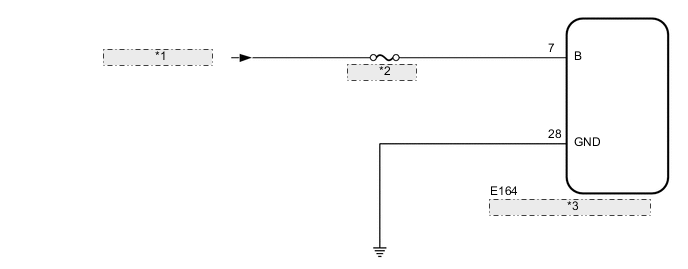
| *1 | from IG NO. 4 Relay |
| *2 | ECU-IG NO. 6 |
| *3 | Driving Support ECU Assembly |
CAUTION / NOTICE / HINT
Note
Inspect the fuses for circuits related to this system before performing the following inspection procedure.
PROCEDURE
-
CUSTOMER PROBLEM ANALYSIS AND SYMPTOM CHECK
-
Check the customer problem analysis and symptom Click here.
NEXT 
-
-
INSPECT BATTERY
-
Measure the battery voltage.
Standard voltage 11 to 14 V -
Using the parts location and system diagram, check the system for blown-out fuses, open or short circuits in the wire harness(es) and connectors that are not properly connected by performing a visual check.
Tech Tips
If the voltage is 11 V or less, replace or recharge the battery before proceeding to the next step.
NEXT
-
-
CHECK HARNESS OR CONNECTOR (DRIVING SUPPORT ECU ASSEMBLY - BATTERY AND BODY GROUND)
Note
As the connector may be damaged if a load of more than 10 kg (22 lb) is applied to it, do not apply any more load than necessary to the connector.
-
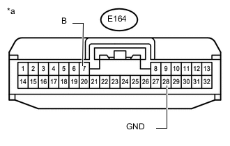
Text in Illustration *a Front view of wire harness connector
(to driving support ECU assembly)
Disconnect the driving support ECU assembly connector.
-
Measure the voltage according to the value(s) in the table below.
Note
DTCs may be output when connectors are disconnected during inspection. Therefore, make sure to clear the DTCs using the GTS once the inspection has been completed.
Standard Voltage Tester Connection Condition Specified Condition E164-7 (B) - Body ground Engine switch on (IG) 11 to 14 V Engine switch off Below 1 V -
Measure the resistance according to the value(s) in the table below.
Standard Resistance Tester Connection Condition Specified Condition E164-28 (GND) - Body ground Always Below 1 Ω
NG 
REPAIR OR REPLACE HARNESS OR CONNECTOR
OK
-
-
CHECK CAN COMMUNICATION SYSTEM
-
Use the GTS to check if the CAN communication system is functioning normally.
-
for LHD: Click here
-
for RHD: Click here
Result Result Proceed to CAN communication system DTCs are not output A CAN communication system DTCs are output (for LHD (w/ Central Gateway ECU)) B CAN communication system DTCs are output (for RHD (w/ Central Gateway ECU)) C -
B
GO TO CAN COMMUNICATION SYSTEM Click here
C
GO TO CAN COMMUNICATION SYSTEM Click here
A
-
-
CHECK DTC OUTPUT
-
Connect the GTS to the DLC3.
-
Turn the engine switch on (IG).
-
Enter the following menus: Body Electrical / Pre-Crash 2 / Trouble Codes.
-
Check the DTCs Click here.
-
Clear for DTCs Click here.
-
Recheck for DTCs. Try to reproduce the DTCs by duplicating the conditions indicated by the DTCs. Click here.
Result Result Proceed to DTCs are not output A DTCs are output B
B
GO TO DIAGNOSTIC TROUBLE CODE CHART
A
-
-
DATA LIST / ACTIVE TEST
-
Using the GTS, check the Data List Click here.
-
Using the GTS, perform the Active Test Click here.
NEXT
-
-
VEHICLE CONTROL HISTORY
-
Check whether the vehicle control history (PCS operation history) matches the customer analysis Click here.
Result Result Proceed to Vehicle control history matches the customer analysis A Vehicle control history does not match customer analysis or there is no vehicle control history B
A
END
B
USE SIMULATION METHOD TO CHECK
-