SPIRAL CABLE INSPECTION
PROCEDURE
-
INSPECT SPIRAL CABLE SUB-ASSEMBLY (w/ Steering Pad Switch)
-
If there are any defects as mentioned below, replace the spiral cable sub-assembly with a new one:
Scratches, cracks, dents or chips on the connector or the spiral cable sub-assembly.
-
Check the spiral cable sub-assembly.
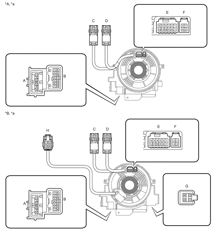
Text in Illustration *A w/ Steering Heater *B w/o Steering Heater *a Component without harness connected
(Spiral Cable sub-assembly)
- - 
Interlock - -
-
Set the spiral cable to the center position.
-
Measure the resistance between each terminal of the spiral cable according to the table below.
-
After setting the spiral cable to the center position, rotate the spiral cable 2.5 times clockwise, and measure the resistance as shown. Then rotate the spiral cable 5 times counterclockwise, and measure the resistance as shown.
Standard Resistance Tester Connection Condition Specified Condition A-1 - C-2 Always Below 1 Ω A-2 - C-1 A-3 - D-1 A-4 - D-2 B-1 - F-3 Below 3 Ω B-2 - E-7 B-2 - F-4 B-3 - E-8 B-4 - E-9 B-5 - E-10 B-6 - E-11 B-7 - E-12 B-8 - F-1 B-9 - E-1 B-9 - F-1 B-10 - E-2 B-11 - E-3 B-12 - E-4 B-13 - E-5 B-14 - E-6 G-1 - H-1 Below 3 Ω G-2 - H-3 Below 0.1 Ω G-3 - H-2 Below 3 Ω G-4 - H-4 Below 0.1 Ω -
After setting the spiral cable to the center position, rotate the spiral cable 2.5 times clockwise. Then while rotating the spiral cable 5 times counterclockwise, measure the resistance as shown.
Standard Resistance Tester Connection Condition Specified Condition A-1 - C-2 Always Below 1 Ω A-2 - C-1 A-3 - D-1 A-4 - D-2 B-1 - F-3 Below 3 Ω B-2 - E-7 B-2 - F-4 B-3 - E-8 B-4 - E-9 B-5 - E-10 B-6 - E-11 B-7 - E-12 B-8 - F-1 B-9 - E-1 B-9 - F-1 B-10 - E-2 B-11 - E-3 B-12 - E-4 B-13 - E-5 B-14 - E-6 G-1 - H-1 Below 3 Ω G-2 - H-3 Below 0.1 Ω G-3 - H-2 Below 3 Ω G-4 - H-4 Below 0.1 Ω If the result is not as specified, replace the spiral cable sub-assembly.
-
-
-
INSPECT SPIRAL CABLE SUB-ASSEMBLY (w/o Steering Pad Switch)
-
If there are any defects as mentioned below, replace the spiral cable sub-assembly with a new one:
Scratches, cracks, dents or chips on the connector or the spiral cable sub-assembly.
-
Check the spiral cable sub-assembly.
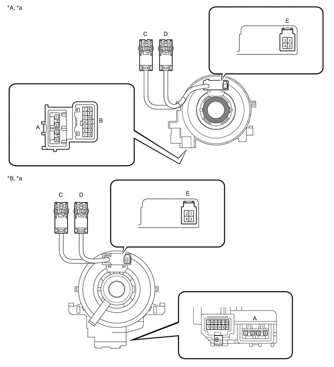
Text in Illustration *A for Type A *B for Type B *a Component without harness connected
(Spiral Cable sub-assembly)
- - Interlock - -
-
Set the spiral cable to the center position.
-
Measure the resistance between each terminal of the spiral cable according to the table below.
-
After setting the spiral cable to the center position, rotate the spiral cable 2.5 times clockwise, and measure the resistance as shown. Then rotate the spiral cable 5 times counterclockwise, and measure the resistance as shown.
Standard Resistance Tester Connection Condition Specified Condition A-1 - C-2 Always Below 1 Ω A-2 - C-1 A-3 - D-1 A-4 - D-2 B-1 - E-3 Below 3 Ω B-2 - E-4 B-9 - E-2 -
After setting the spiral cable to the center position, rotate the spiral cable 2.5 times clockwise. Then while rotating the spiral cable 5 times counterclockwise, measure the resistance as shown.
Standard Resistance Tester Connection Condition Specified Condition A-1 - C-2 Always Below 1 Ω A-2 - C-1 A-3 - D-1 A-4 - D-2 B-1 - E-3 Below 3 Ω B-2 - E-4 B-9 - E-2 If the result is not as specified, replace the spiral cable sub-assembly.
-
-