AIRBAG SYSTEM Diagnosis Circuit
DESCRIPTION
DTC output mode is set by connecting terminals TC and CG of the DLC3.
DTCs are output by the blinking of the SRS warning light.
Tech Tips
-
When each warning light stays blinking, a ground short in the wiring of terminal TC of the DLC3 or an internal ground short in each ECU is suspected.
-
A DTC output mode signal is transmitted through the CAN communication system to each ECU including the center airbag sensor. Thus, when all systems do not enter DTC output mode, there may be an ECM malfunction.
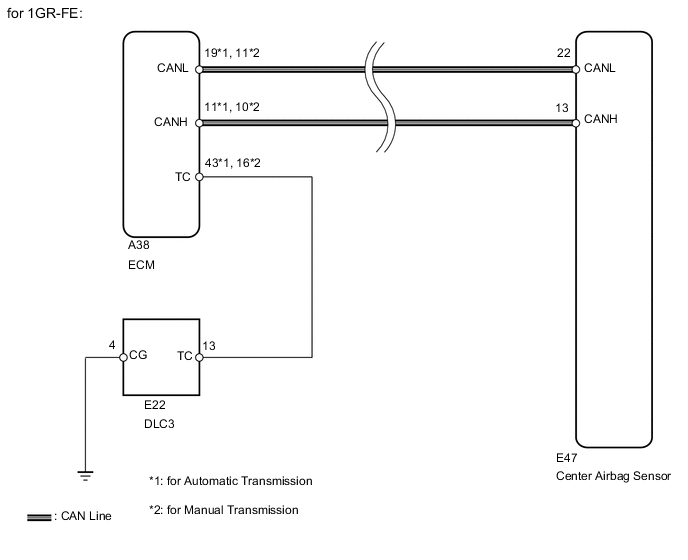
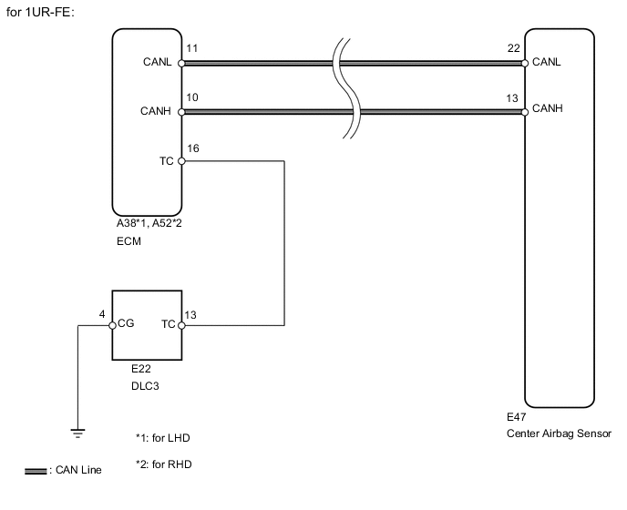
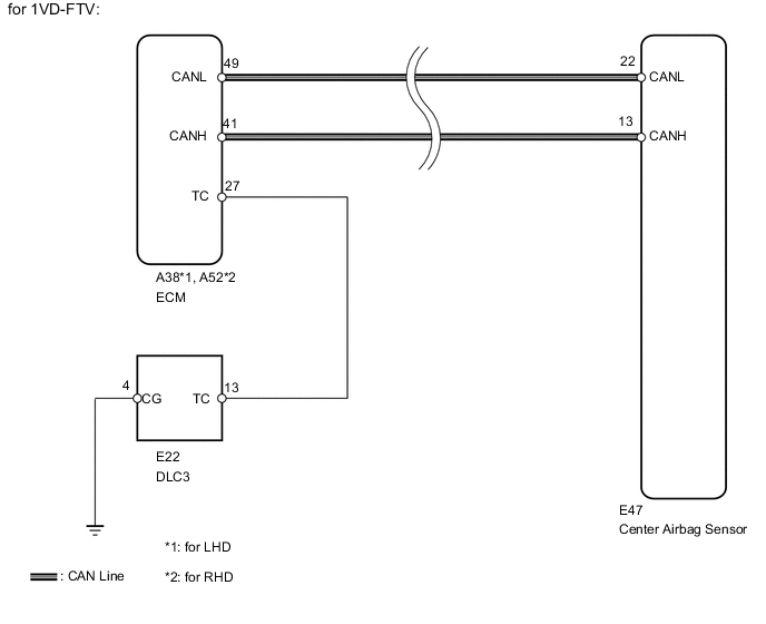
WIRING DIAGRAM
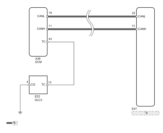
| *a | Center Airbag Sensor |
| *b | CAN Line |
CAUTION / NOTICE / HINT
Note
-
After turning the ignition switch off, waiting time may be required before disconnecting the cable from the battery terminal. Therefore, make sure to read the disconnecting the cable from the battery terminal notice before proceeding with work Click here.
-
When disconnecting the cable, some systems need to be initialized after the cable is reconnected Click here.
-
After replacing the center airbag sensor assembly, refer to initialization Click here.
PROCEDURE
-
CHECK CAN COMMUNICATION SYSTEM
-
Check if a CAN communication system DTC is output.
Result Result Proceed to DTC is not output A DTC is output (for LHD with Central Gateway ECU) B DTC is output (for RHD with Central Gateway ECU) C DTC is output (for LHD without Central Gateway ECU) D DTC is output (for RHD without Central Gateway ECU) E
B 
REPAIR CIRCUITS INDICATED BY OUTPUT DTCS Click here
C
REPAIR CIRCUITS INDICATED BY OUTPUT DTCS Click here
D
REPAIR CIRCUITS INDICATED BY OUTPUT DTCS Click here
E
REPAIR CIRCUITS INDICATED BY OUTPUT DTCS Click here
A 
-
-
CHECK HARNESS AND CONNECTOR (DLC3 - ECM)
-
Turn the ignition switch off.
-
Disconnect the connector from the ECM.
-
for LHD:
-
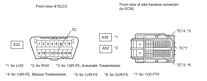
Measure the resistance according to the value(s) in the table below.
Standard Resistance for 1GR-FE, Automatic Transmission Tester Connection Condition Specified Condition E22-13 (TC) - A38-43 (TC) Always Below 1 Ω for 1GR-FE, Manual Transmission Tester Connection Condition Specified Condition E22-13 (TC) - A38-16 (TC) Always Below 1 Ω for 1UR-FE Tester Connection Condition Specified Condition E22-13 (TC) - A38-16 (TC) Always Below 1 Ω for 3UR-FE Tester Connection Condition Specified Condition E22-13 (TC) - A38-43 (TC) Always Below 1 Ω for 1VD-FTV Tester Connection Condition Specified Condition E22-13 (TC) - A38-27 (TC) Always Below 1 Ω
-
-
for RHD:
-
Measure the resistance according to the value(s) in the table below.
Standard Resistance for 1UR-FE Tester Connection Condition Specified Condition E22-13 (TC) - A52-16 (TC) Always Below 1 Ω for 1VD-FTV Tester Connection Condition Specified Condition E22-13 (TC) - A52-27 (TC) Always Below 1 Ω
-
NG
REPAIR OR REPLACE HARNESS OR CONNECTOR
OK
-
-
CHECK HARNESS AND CONNECTOR (DLC3 - BODY GROUND)
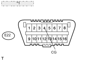
*1 Front view of DLC3:
-
Measure the resistance according to the value(s) in the table below.
Standard Resistance Tester Connection Condition Specified Condition E22-4 (CG) - Body ground Always Below 1 Ω
NG
REPAIR OR REPLACE HARNESS OR CONNECTOR
OK
-
-
CHECK HARNESS AND CONNECTOR (TC OF ECM - BODY GROUND)
-
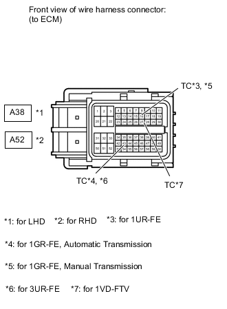
for LHD:
-
Measure the resistance according to the value(s) in the table below.
Standard Resistance for 1GR-FE, Automatic Transmission Tester Connection Condition Specified Condition A38-43 (TC) - Body ground Always 1 MΩ or higher for 1GR-FE, Manual Transmission Tester Connection Condition Specified Condition A38-16 (TC) - Body ground Always 1 MΩ or higher for 1UR-FE Tester Connection Condition Specified Condition A38-16 (TC) - Body ground Always 1 MΩ or higher for 3UR-FE Tester Connection Condition Specified Condition A38-43 (TC) - Body ground Always 1 MΩ or higher for 1VD-FTV Tester Connection Condition Specified Condition A38-27 (TC) - Body ground Always 1 MΩ or higher
-
-
for RHD:
-
Measure the resistance according to the value(s) in the table below.
Standard Resistance for 1UR-FE Tester Connection Condition Specified Condition A52-16 (TC) - Body ground Always 1 MΩ or higher 1VD-FTV Tester Connection Condition Specified Condition A52-27 (TC) - Body ground Always 1 MΩ or higher
-
OK
REPLACE CENTER AIRBAG SENSOR ASSEMBLY Click here
NG
REPAIR OR REPLACE HARNESS OR CONNECTOR OR EACH ECU
-