SPIRAL CABLE INSTALLATION
CAUTION / NOTICE / HINT
Tech Tips
-
Use the same procedure for RHD and LHD vehicles.
-
The procedure listed below is for LHD vehicles.
PROCEDURE
-
INSPECT SPIRAL CABLE SUB-ASSEMBLY (for Interlock Type)
-
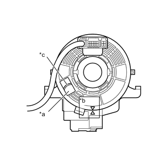
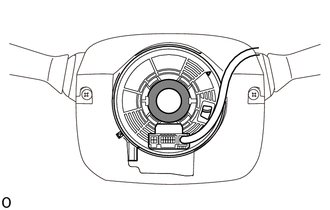
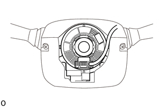
Check that the spiral cable sub-assembly is center position.
OK The connector is at the top. The matchmarks are aligned. The colored roller or the top of the flat cable U-turn can be checked from the check window. 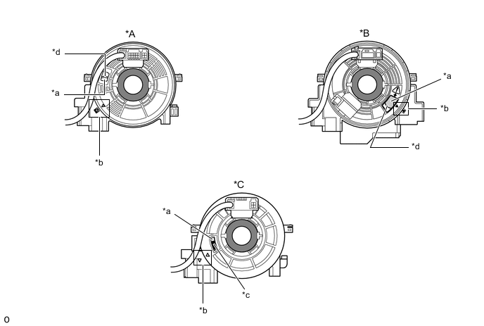
*A Flat Cable (Visible Type), w/o Steering Haeter *B Flat Cable (Visible Type), w/ Steering Heater *C Colored Roller (Visible Type) - - *a Check Window *b Matchmark *c Colored Roller *d Top of Flat Cable U-turn -
If the spiral cable sub-assembly is not centered, center it.
Note
Failure to observe the following precautions may result in damage to the spiral cable sub-assembly .
-
When rotating the spiral cable sub-assembly , make sure to push on the interlock to release the interlock.
-
Do not turn the spiral cable sub-assembly using the airbag wire harness.
-
Do not forcibly rotate the part.
-
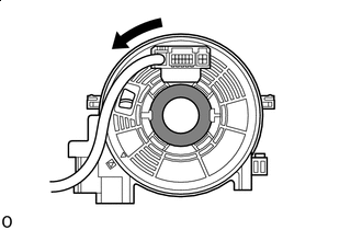

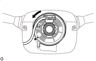
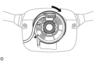
Interlock 
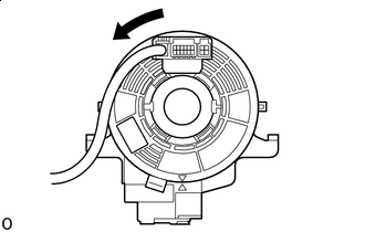
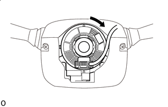
Counterclockwise While pushing on the interlock indicated in the illustration. Make sure to rotate the spiral cable sub-assembly counterclockwise slowly by hand until it stops.
Note
Make sure to rotate the spiral cable sub-assembly counterclockwise. If rotated clockwise, it may be damaged or centering may no longer be possible.
Tech Tips
The interlock operates at the top and bottom of the connector.
-
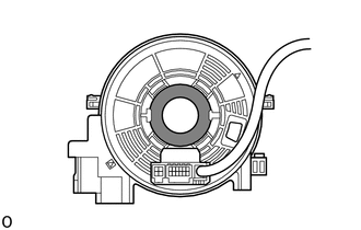
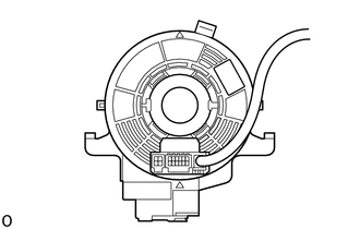
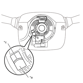
If the spiral cable sub-assembly stops rotating and the connector has moved past the bottom, return the connector to the bottom as shown in the illustration.
-
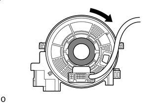
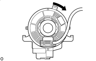
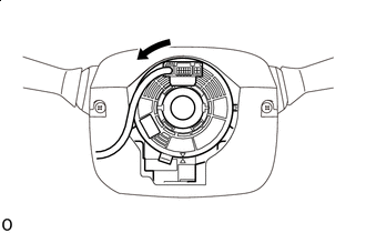
Interlock Counterclockwise While pushing on the interlock, rotate the spiral cable sub-assembly clockwise approximately 2.5 times to move the connector from the bottom to the top.
Note
If the connector is rotated clockwise from the bottom 5 times or more, the spiral cable sub-assembly may be damaged.
Tech Tips
The interlock operates at the top and bottom of the connector.
-
-
Check that the spiral cable sub-assembly is center position.
OK The connector is at the top. The matchmarks are aligned. The colored roller or the top of the flat cable U-turn can be checked from the check window.
*A Flat Cable (Visible Type), w/o Steering Haeter *B Flat Cable (Visible Type), w/ Steering Heater *C Colored Roller (Visible Type) - - *a Check Window *b Matchmark *c Colored Roller *d Top of Flat Cable U-turn Note
If the spiral cable sub-assembly cannot be centered, it is possible that the spiral cable sub-assembly is broken. Replace the spiral cable sub-assembly with a new one.
-
-
INSPECT SPIRAL CABLE SUB-ASSEMBLY (for Pin Lock Type)
-
*a Check Window *b Matchmark *c Top of Flat Cable U-turn Check that the spiral cable sub-assembly is center position.
OK The connector is at the top. The matchmarks are aligned. The top of the flat cable U-turn can be checked from the check window. -
If the spiral cable sub-assembly is not centered, center it.
Note
Failure to observe the following precautions may result in damage to the spiral cable sub-assembly.
-
Do not turn the spiral cable sub-assembly using the airbag wire harness.
-
Do not forcibly rotate the part.
-
Counterclockwise Make sure to rotate the spiral cable sub-assembly counterclockwise slowly by hand until it stops.
Note
Make sure to rotate the spiral cable sub-assembly counterclockwise. If rotated clockwise, it may be damaged or centering may no longer be possible.
-
If the spiral cable sub-assembly stops rotating and the connector has moved past the bottom, return the connector to the bottom as shown in the illustration.
-
Clockwise Rotate the spiral cable sub-assembly clockwise approximately 2.5 times to move the connector from the bottom to the top.
Note
If the connector is rotated clockwise from the bottom 5 times or more, the spiral cable sub-assembly may be damaged.
-
*a Check Window *b Matchmark *c Top of Flat Cable U-turn Check that the spiral cable sub-assembly is center position.
OK The connector is at the top. The matchmarks are aligned. The top of the flat cable U-turn can be checked from the check window. Note
If the spiral cable sub-assembly cannot be centered, it is possible that the spiral cable sub-assembly is broken. Replace the spiral cable sub-assembly with a new one.
-
-
-
INSTALL SPIRAL CABLE (w/ Steering Angle Sensor)
Note
If the steering sensor is installed to a misaligned spiral cable, DTCs for an abnormal steering sensor value such as DTC C1433 are stored and it is impossible to repair them. If this happens, replace the spiral cable sub-assembly with a new one.
-
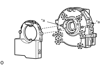
*a Pin Align the 2 pins of the spiral cable with the locations shown in the illustration and attach the 6 claws to install the spiral cable to the steering sensor.
Note
Do not remove the lock pin before the spiral cable is installed to the steering sensor.
-
Remove the lock pin from the steering sensor.
-
-
INSTALL SPIRAL CABLE SUB-ASSEMBLY
Note
-
Do not replace the spiral cable sub-assembly with sensor with the battery connected and the ignition switch on.
-
Do not rotate the spiral cable sub-assembly with sensor with the battery connected and the ignition switch on.
-
When rotating the spiral cable sub-assembly with sensor to check the operation of the spiral cable sub-assembly (checking for abnormal noise, checking the DTC, Data list, etc.) make sure to perform the inspection with the steering wheel assembly installed.
-
*a Lock Pin for Pin Lock Type:
When replacing the spiral cable sub-assembly with sensor with a new one, remove the lock pin before installing the steering wheel assembly.
-
Set the turn signal switch to the neutral position.
Note
If it is not in the neutral position, the pin of the turn signal switch may be snapped.
-
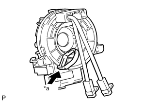
Attach the 3 claws to install the spiral cable sub-assembly.
-
Connect each connector.
Note
When handling the airbag connector, take care not to damage the airbag wire harness.
-
-
ADJUST SPIRAL CABLE (for Interlock Type)
Note
Do not adjust the spiral cable sub-assembly with the battery connected and the ignition switch ON.
-
Check that the ignition switch is off.
-
Check that the cable is disconnected from the battery negative (-) terminal.
CAUTION:
Wait at least 90 seconds after disconnecting the cable from the negative (-) battery terminal to disable the SRS system.
-
Check that the spiral cable sub-assembly is center position.
OK The connector is at the top. The colored roller or the top of the flat cable U-turn can be checked from the check window. 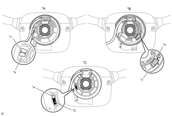
*A Flat Cable (Visible Type), w/o Steering Haeter *B Flat Cable (Visible Type), w/ Steering Heater *C Colored Roller (Visible Type) - - *a Check Window *b Colored Roller *c Top of Flat Cable U-turn - - -
If the spiral cable sub-assembly is not centered, center it.
Note
Failure to observe the following precautions may result in damage to the spiral cable sub-assembly.
-
When rotating the spiral cable sub-assembly, make sure to push on the interlock to release the interlock.
-
Do not turn the spiral cable sub-assembly using the airbag wire harness.
-
Do not forcibly rotate the part.
-
Interlock Counterclockwise While pushing on the interlock indicated in the illustration. Make sure to rotate the spiral cable sub-assembly counterclockwise slowly by hand until it stops.
Note
If the connector is rotated clockwise from the bottom 5 times or more, the spiral cable sub-assembly may be damaged.
Tech Tips
The interlock operates at the top and bottom of the connector.
-
If the spiral cable sub-assembly stops rotating and the connector has moved past the bottom, return the connector to the bottom as shown in the illustration.
-
Interlock Clockwise While pushing on the interlock, rotate the spiral cable sub-assembly clockwise approximately 2.5 times to move the connector from the bottom to the top.
Note
If the connector is rotated clockwise from the bottom 5 times or more, the spiral cable sub-assembly may be damaged.
Tech Tips
The interlock operates at the top and bottom of the connector.
-
Check that the spiral cable sub-assembly is center position.
OK The connector is at the top. The colored roller or the top of the flat cable U-turn can be checked from the check window.
*A Flat Cable (Visible Type), w/o Steering Haeter *B Flat Cable (Visible Type), w/ Steering Heater *C Colored Roller (Visible Type) - - *a Check Window *b Colored Roller *c Top of Flat Cable U-turn - - Note
If the spiral cable sub-assembly cannot be centered, it is possible that the spiral cable sub-assembly is broken. Replace the spiral cable sub-assembly with a new one.
-
-
-
ADJUST SPIRAL CABLE (for Pin Lock Type)
-
Check that the ignition switch is off.
-
Check that the cable is disconnected from the negative (-) battery terminal.
CAUTION:
Wait at least 90 seconds after disconnecting the cable from the negative (-) battery terminal to disable the SRS system.
-
*a Check Window *b Matchmark *c Top of Flat Cable U-turn Check that the spiral cable sub-assembly is center position.
OK The connector is at the top. The matchmarks are aligned. The top of the flat cable U-turn can be checked from the check window. -
If the spiral cable sub-assembly is not centered, center it.
Note
Failure to observe the following precautions may result in damage to the spiral cable sub-assembly.
-
Do not turn the spiral cable sub-assembly using the airbag wire harness.
-
Do not forcibly rotate the part.
-
Counterclockwise Make sure to rotate the spiral cable sub-assembly counterclockwise slowly by hand until it stops.
Note
Make sure to rotate the spiral cable sub-assembly counterclockwise. If rotated clockwise, it may be damaged or centering may no longer be possible.
-
If the spiral cable sub-assembly stops rotating and the connector has moved past the bottom, return the connector to the bottom as shown in the illustration.
-
Clockwise Rotate the spiral cable sub-assembly clockwise approximately 2.5 times to move the connector from the bottom to the top.
Note
If the connector is rotated clockwise from the bottom 5 times or more, the spiral cable sub-assembly may be damaged.
-
*a Check Window *b Matchmark *c Top of Flat Cable U-turn Check that the spiral cable sub-assembly is center position.
OK The connector is at the top. The matchmarks are aligned. The top of the flat cable U-turn can be checked from the check window. Note
If the spiral cable sub-assembly cannot be centered, it is possible that the spiral cable sub-assembly is broken. Replace the spiral cable sub-assembly with a new one.
-
-
-
INSTALL UPPER STEERING COLUMN COVER
for Manual Tilt and Manual Telescopic Steering Column:
for Power Tilt and Power Telescopic Steering Column:
-
INSTALL LOWER STEERING COLUMN COVER
for Manual Tilt and Manual Telescopic Steering Column:
for Power Tilt and Power Telescopic Steering Column:
-
INSTALL STEERING WHEEL ASSEMBLY
-
CONNECT CABLE TO NEGATIVE BATTERY TERMINAL
Note
When disconnecting the cable, some systems need to be initialized after the cable is reconnected Click here.
-
INSPECT STEERING PAD
-
CHECK SRS WARNING LIGHT
-
Check the SRS warning light Click here.
-