INNER REAR VIEW MIRROR INSPECTION
PROCEDURE
-
REMOVE INNER REAR VIEW MIRROR ASSEMBLY (for Standard)
-
Check operation of the electrochromic inner mirror.
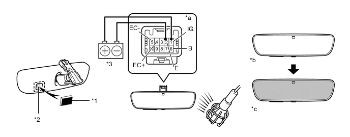
Text in Illustration *1 Black Colored Tape *2 Forward Sensor *3 Battery - - *a Component without harness connected (Inner Rear View Mirror Assembly) *b Bright *c Dark - -
-
Connect the battery positive (+) lead to terminal 1 (IG) and the negative (-) lead to terminal 2 (E).
-
Press the AUTO switch.
-
Attach black colored tape to the forward sensor to prevent it from sensing light.
-
Shine an electric light on the mirror. Check that the mirror surface changes from bright to dark.
Tech Tips
When the environment is very bright, the antiglare operation may occur immediately after the tape is applied.
-
Measure the voltage according to the value(s) in the table below.
Standard Voltage Tester Connection Condition Specified Condition 4 - 5 Inner rear view mirror surface
Bright → Dark
Below 1 V → 1.25 V If the result is not as specified, replace the inner rear view mirror assembly.
-
-
-
INSPECT INNER REAR VIEW MIRROR ASSEMBLY (w/ Adaptive High Beam System)
-
Check operation of the electrochromic inner mirror.
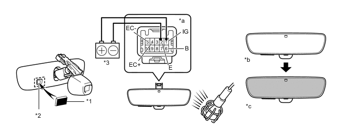
Text in Illustration *1 Black Colored Tape *2 Forward Sensor *3 Battery - - *a Component without harness connected (Inner Rear View Mirror Assembly) *b Bright *c Dark - -
-
Connect the battery positive (+) lead to terminal 1 (IG) and the negative (-) lead to terminal 2 (E).
-
Press the AUTO switch.
-
Attach black colored tape to the forward sensor to prevent it from sensing light.
-
Shine an electric light on the mirror. Check that the mirror surface changes from bright to dark.
Tech Tips
When the environment is very bright, the antiglare operation may occur immediately after the tape is applied.
-
Measure the voltage according to the value(s) in the table below.
Standard Voltage Tester Connection Condition Specified Condition 4 - 5 Inner rear view mirror surface
Bright → Dark
Below 1 V → 1.25 V If the result is not as specified, replace the inner rear view mirror assembly.
-
-
-
REMOVE INNER REAR VIEW MIRROR ASSEMBLY (w/ Pre-collision System)
-
Check operation of the electrochromic inner mirror.
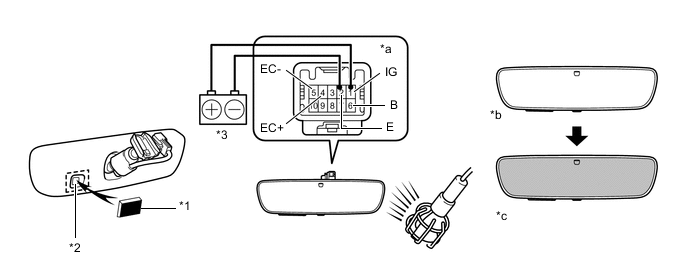
Text in Illustration *1 Black Colored Tape *2 Forward Sensor *3 Battery - - *a Component without harness connected (Inner Rear View Mirror Assembly) *b Bright *c Dark - -
-
Connect the battery positive (+) lead to terminal 1 (IG) and the negative (-) lead to terminal 2 (E).
-
Press the AUTO switch.
-
Attach black colored tape to the forward sensor to prevent it from sensing light.
-
Shine an electric light on the mirror. Check that the mirror surface changes from bright to dark.
Tech Tips
When the environment is very bright, the antiglare operation may occur immediately after the tape is applied.
-
Measure the voltage according to the value(s) in the table below.
Standard Voltage Tester Connection Condition Specified Condition 4 (EC+) - 5 (EC-) Inner rear view mirror surface
Bright → Dark
Below 1 V → 1.25 V If the result is not as specified, replace the inner rear view mirror assembly.
-
-