METER / GAUGE SYSTEM, Diagnostic DTC:B1507, B1508
| DTC Code | DTC Name |
|---|---|
| B1507 | Open in Turn Signal Circuit |
| B1508 | Short in Turn Signal / Hazard Flasher Circuit |
DESCRIPTION
These DTCs are stored when the combination meter assembly detects an open in a turn signal light circuit, a short in a turn signal light circuit, or a short in the hazard warning light circuit.
| DTC No. | DTC Detection Condition | Trouble Area |
|---|---|---|
| B1507 | When IG voltage is 9.5 V or more and the following condition is detected:
|
|
| B1508 | When IG voltage is 9.5 V or more and the following condition is detected:
|
|
-
*1: w/ Retract Mirror
-
*2: except Double Swing Out Type
-
*3: for Outer Rear View Mirror
-
*4: w/ Towing Package
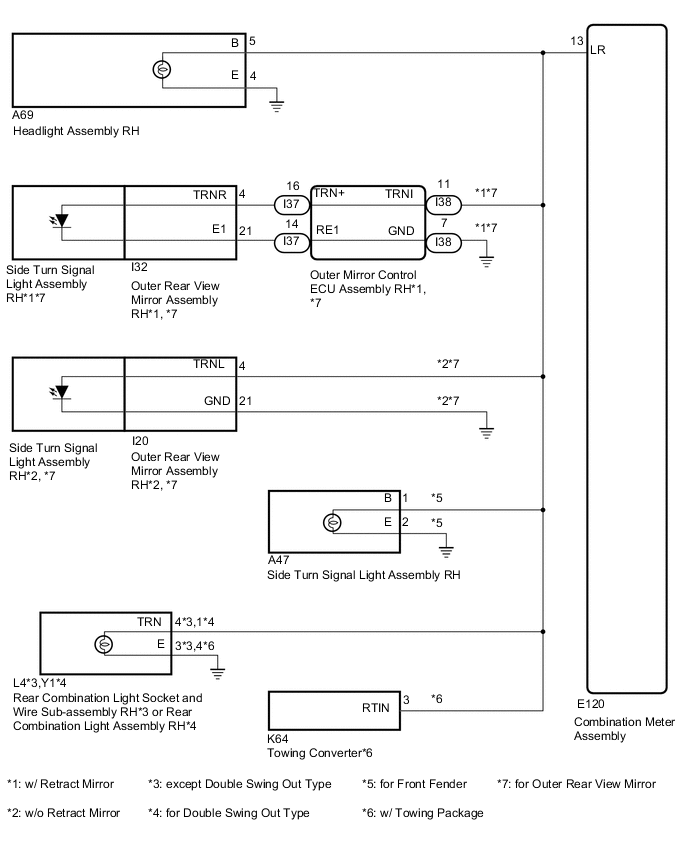
WIRING DIAGRAM
-
RH Side
-
LH Side

CAUTION / NOTICE / HINT
Note
Inspect the bulbs for this system before performing the following inspection procedure.
PROCEDURE
-
CHECK DTC
-
Clear the DTCs.
-
Recheck for DTCs and check that no DTCs are output.
Result Result Proceed to B1507 and B1508 are output A B1507 and B1508 are not output B
B 
USE SIMULATION METHOD TO CHECK Click here
A 
-
-
INSPECT LIGHTS
-
Inspect the illumination of each turn signal light.
Result Result Proceed to RH side turn signal light does not illuminate A LH side turn signal light does not illuminate B
B 
CHECK HARNESS AND CONNECTOR (TURN SIGNAL CIRCUIT LH) Click here
A
-
-
CHECK HARNESS AND CONNECTOR (TURN SIGNAL CIRCUIT RH)
-
*1: w/ Retract Mirror
-
*2: w/o Retract Mirror
-
*3: except Double Swing Out Type
-
*4: for Double Swing Out Type
-
*5: for Front Fender
-
*6: w/ Towing Package
-
*7: for Outer Rear View Mirror
-
Disconnect the E120 combination meter assembly connector.
-
Disconnect the A69 headlight assembly RH connector.
-
Disconnect the I20*2 or I32*1 outer rear view mirror assembly RH connector.*7
-
Disconnect the A47 side turn signal light assembly RH connector.*5
-
Disconnect the L4*3 or Y1*4 rear combination light assembly RH connector.
-
Disconnect the K64 towing converter connector.*6
-
Measure the resistance according to the value(s) in the table below.
Standard Resistance Tester Connection Condition Specified Condition A69-5 (B) - E120-13 (LR) Always Below 1 Ω A69-4 (E) - Body ground Always Below 1 Ω I20-4 (TRNL) - E120-13 (LR) Always Below 1 Ω I20-21 (GND) - Body ground Always Below 1 Ω I32-4 (TRNR) - E120-13 (LR) Always Below 1 Ω I32-21 (E1) - Body ground Always Below 1 Ω A47-1 (B) - E120-13 (LR) Always Below 1 Ω A47-2 (E) - Body ground Always Below 1 Ω L4-4 (TRN) - E120-13 (LR) Always Below 1 Ω L4-3 (E) - Body ground Always Below 1 Ω Y1-1 (TRN) - E120-13 (LR) Always Below 1 Ω Y1-4 (E) - Body ground Always Below 1 Ω K64-3 (RTIN) - E120-13 (LR) Always Below 1 Ω E120-13 (LR) - Body ground Always 10 kΩ or higher Result Result Proceed to OK A NG (for Outer Rear View Mirror with Retract Mirror) B NG (except Outer Rear View Mirror with Retract Mirror) C
B
CHECK HARNESS AND CONNECTOR (TURN SIGNAL CIRCUIT RH) Click here
C
REPAIR OR REPLACE HARNESS AND CONNECTOR
A
-
-
INSPECT HEADLIGHT ASSEMBLY RH
-
Remove the headlight assembly RH.
-
for Halogen Headlight Click here
-
for LED Headlight Click here
-
for Halogen Headlight and LED Headlight Click here
-
-
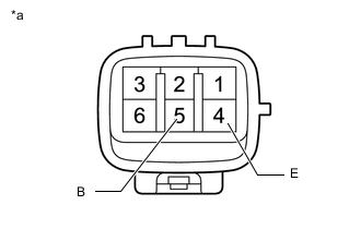
Text in Illustration *a Component without harness connected
(Headlight Assembly RH)
Apply battery voltage between the terminals and check the light illumination condition.
OK Condition Specified Condition Battery positive (+) →5 (B)
Battery positive (-) →4 (E)
Turn signal light illuminates Result Result Proceed to OK (for Outer Rear View Mirror) A OK (for Front Fender) B NG (for Halogen Headlight) C NG (for LED Headlight) D NG (for Halogen Headlight and LED Headlight) E
B
CHECK VEHICLE TYPE Click here
C
REPLACE HEADLIGHT ASSEMBLY RH Click here
D
REPLACE HEADLIGHT ASSEMBLY RH Click here
E
REPLACE HEADLIGHT ASSEMBLY RH Click here
A
-
-
INSPECT OUTER REAR VIEW MIRROR ASSEMBLY RH
-
Remove the outer rear view mirror assembly RH.
-
Inspect the outer rear view mirror assembly RH.
NG
REPLACE OUTER REAR VIEW MIRROR ASSEMBLY RH Click here
OK
-
-
CHECK VEHICLE TYPE
-
Check the vehicle type.
Result Result Proceed to except Double Swing Out Type A for Double Swing Out Type B
B
CHECK VEHICLE TYPE Click here
A
-
-
INSPECT REAR COMBINATION LIGHT SOCKET AND WIRE SUB-ASSEMBLY RH
-
Remove the rear combination light socket and wire subassembly RH Click here.
-
Install the turn signal light bulb to the rear combination light socket and wire sub-assembly RH.
-
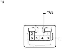
Text in Illustration *a Component without harness connected
(Rear Combination Light Socket and Wire Sub-assembly RH)
Apply battery voltage between the terminals and check the light illumination condition.
OK Condition Specified Condition Battery positive (+) →4 (TRN)
Battery positive (-) →3 (E)
Turn signal light illuminates
NG
REPLACE REAR COMBINATION LIGHT SOCKET AND WIRE SUB-ASSEMBLY RH Click here
OK
-
-
CHECK VEHICLE TYPE
-
Check the vehicle type.
Result Result Proceed to w/ Towing Package A w/o Towing Package B
B
REPLACE COMBINATION METER ASSEMBLY Click here
A
-
-
CHECK TOWING CONVERTER
-
Replace the towing converter.
-
Clear the DTCs.
-
Check for DTCs and check that no DTCs are output.
OK
END (TOWING CONVERTER IS DEFECTIVE)
NG
REPLACE COMBINATION METER ASSEMBLY Click here
-
-
CHECK HARNESS AND CONNECTOR (TURN SIGNAL CIRCUIT RH)
-
*1: except Double Swing Out Type
-
*2: for Double Swing Out Type
-
*3: w/ Towing Package
-
Disconnect the E120 combination meter assembly connector.
-
Disconnect the A69 headlight assembly RH connector.
-
Disconnect the I38 outer mirror control ECU assembly RH connector.
-
Disconnect the L4*1 or Y1*2 rear combination light assembly RH connector.
-
Disconnect the K64 towing converter connector.*3
-
Measure the resistance according to the value(s) in the table below.
Standard Resistance Tester Connection Condition Specified Condition A69-5 (B) - E120-13 (LR) Always Below 1 Ω A69-4 (E) - Body ground Always Below 1 Ω I38-11 (TRNI) - E120-13 (LR) Always Below 1 Ω I38-7 (GND) - Body ground Always Below 1 Ω L4-4 (TRN) - E120-13 (LR) Always Below 1 Ω L4-3 (E) - Body ground Always Below 1 Ω Y1-1 (TRN) - E120-13 (LR) Always Below 1 Ω Y1-4 (E) - Body ground Always Below 1 Ω K64-3 (RTIN) - E120-13 (LR) Always Below 1 Ω E120-13 (LR) - Body ground Always 10 kΩ or higher
NG
REPAIR OR REPLACE HARNESS AND CONNECTOR
OK
-
-
CHECK HARNESS AND CONNECTOR (TURN SIGNAL CIRCUIT RH)
-
Disconnect the I37 outer mirror control ECU assembly RH connector.
-
Disconnect the I32 outer rear view mirror assembly RH connector.
-
Measure the resistance according to the value(s) in the table below.
Standard Resistance Tester Connection Condition Specified Condition I37-16 (TRN+) - I32-4 (TRNR) Always Below 1 Ω I37-14 (RE1) - I32-21 (E1) Always Below 1 Ω I37-16 (TRN+) or I32-4 (TRNR) - I37-14 (RE1) or I32-21 (E1) Always 10 kΩ or higher
OK
REPLACE OUTER MIRROR CONTROL ECU ASSEMBLY RH Click here
NG
REPAIR OR REPLACE HARNESS AND CONNECTOR
-
-
CHECK HARNESS AND CONNECTOR (TURN SIGNAL CIRCUIT LH)
-
*1: w/ Retract Mirror
-
*2: w/o Retract Mirror
-
*3: except Double Swing Out Type
-
*4: for Double Swing Out Type
-
*5: for Front Fender
-
*6: w/ Towing Package
-
*7: for Outer Rear View Mirror
-
Disconnect the E120 combination meter assembly connector.
-
Disconnect the A66 headlight assembly LH connector.
-
Disconnect the I21*2 or I35*1 outer rear view mirror assembly LH connector.*7
-
Disconnect the A45 side turn signal light assembly LH connector.*5
-
Disconnect the K4*3 or n1*4 rear combination light assembly LH connector.
-
Disconnect the K64 towing converter connector.*6
-
Measure the resistance according to the value(s) in the table below.
Standard Resistance Tester Connection Condition Specified Condition A66-5 (B) - E120-7 (LL) Always Below 1 Ω A66-4 (E) - Body ground Always Below 1 Ω I21-4 (TRNL) - E120-7 (LL) Always Below 1 Ω I21-21 (GND) - Body ground Always Below 1 Ω I35-4 (TRNL) - E120-7 (LL) Always Below 1 Ω I35-21 (E1) - Body ground Always Below 1 Ω A45-1 (B) - E120-7 (LL) Always Below 1 Ω A45-2 (E) - Body ground Always Below 1 Ω K4-4 (TRN) - E120-7 (LL) Always Below 1 Ω K4-3 (E) - Body ground Always Below 1 Ω n1-1 (TRN) - E120-7 (LL) Always Below 1 Ω n1-4 (E) - Body ground Always Below 1 Ω K64-9 (LTIN) - E120-7 (LL) Always Below 1 Ω E120-7 (LL) - Body ground Always 10 kΩ or higher Result Result Proceed to OK A NG (for Outer Rear View Mirror with Retract Mirror) B NG (except Outer Rear View Mirror with Retract Mirror) C
B
CHECK HARNESS AND CONNECTOR (TURN SIGNAL CIRCUIT LH) Click here
C
REPAIR OR REPLACE HARNESS AND CONNECTOR
A
-
-
INSPECT HEADLIGHT ASSEMBLY LH
-
Remove the headlight assembly LH.
-
for Halogen Headlight Click here
-
for LED Headlight Click here
-
for Halogen Headlight and LED Headlight Click here
-
-
Text in Illustration *a Component without harness connected
(Headlight Assembly LH)
Apply battery voltage between the terminals and check the light illumination condition.
OK Condition Specified Condition Battery positive (+) →5 (B)
Battery positive (-) →4 (E)
Turn signal light illuminates Result Result Proceed to OK (for Outer Rear View Mirror) A OK (for Front Fender) B NG (for Halogen Headlight) C NG (for LED Headlight) D NG (for Halogen Headlight and LED Headlight) E
B
CHECK VEHICLE TYPE Click here
C
REPLACE HEADLIGHT ASSEMBLY LH Click here
D
REPLACE HEADLIGHT ASSEMBLY LH Click here
E
REPLACE HEADLIGHT ASSEMBLY LH Click here
A
-
-
INSPECT OUTER REAR VIEW MIRROR ASSEMBLY LH
-
Remove the outer rear view mirror assembly LH.
-
Inspect the outer rear view mirror assembly LH.
NG
REPLACE OUTER REAR VIEW MIRROR ASSEMBLY LH Click here
OK
-
-
CHECK VEHICLE TYPE
-
Check the vehicle type.
Result Result Proceed to except Double Swing Out Type A for Double Swing Out Type B
B
CHECK VEHICLE TYPE Click here
A
-
-
INSPECT REAR COMBINATION LIGHT SOCKET AND WIRE SUB-ASSEMBLY LH
-
Remove the rear combination light socket and wire subassembly LH Click here.
-
Install the turn signal light bulb to the rear combination light socket and wire sub-assembly LH.
-
Text in Illustration *a Component without harness connected
(Rear Combination Light Socket and Wire Sub-assembly LH)
Apply battery voltage between the terminals and check the light illumination condition.
OK Condition Specified Condition Battery positive (+) →4 (TRN)
Battery positive (-) →3 (E)
Turn signal light illuminates
NG
REAR COMBINATION LIGHT SOCKET AND WIRE SUB-ASSEMBLY LH Click here
OK
-
-
CHECK VEHICLE TYPE
-
Check the vehicle type.
Result Result Proceed to w/ Towing Package A w/o Towing Package B
B
REPLACE COMBINATION METER ASSEMBLY Click here
A
-
-
CHECK TOWING CONVERTER
-
Replace the towing converter.
-
Clear the DTCs.
-
Check for DTCs and check that no DTCs are output.
OK
END (TOWING CONVERTER IS DEFECTIVE)
NG
REPLACE COMBINATION METER ASSEMBLY Click here
-
-
CHECK HARNESS AND CONNECTOR (TURN SIGNAL CIRCUIT LH)
-
*1: except Double Swing Out Type
-
*2: for Double Swing Out Type
-
*3: w/ Towing Package
-
Disconnect the E120 combination meter assembly connector.
-
Disconnect the A66 headlight assembly LH connector.
-
Disconnect the I41 outer mirror control ECU assembly LH connector.
-
Disconnect the K4*1 or n1*2 rear combination light assembly LH connector.
-
Disconnect the K64 towing converter connector.*3
-
Measure the resistance according to the value(s) in the table below.
Standard Resistance Tester Connection Condition Specified Condition A66-5 (B) - E120-7 (LL) Always Below 1 Ω A66-4 (E) - Body ground Always Below 1 Ω I41-11 (TRNI) - E120-7 (LL) Always Below 1 Ω I41-7 (GND) - Body ground Always Below 1 Ω K4-4 (TRN) - E120-7 (LL) Always Below 1 Ω K4-3 (E) - Body ground Always Below 1 Ω n1-1 (TRN) - E120-7 (LL) Always Below 1 Ω n1-4 (E) - Body ground Always Below 1 Ω K64-9 (LTIN) - E120-7 (LL) Always Below 1 Ω E120-7 (LL) - Body ground Always 10 kΩ or higher
NG
REPAIR OR REPLACE HARNESS AND CONNECTOR
OK
-
-
CHECK HARNESS AND CONNECTOR (TURN SIGNAL CIRCUIT RH)
-
Disconnect the I40 outer mirror control ECU assembly LH connector.
-
Disconnect the I35 outer rear view mirror assembly LH connector.
-
Measure the resistance according to the value(s) in the table below.
Standard Resistance Tester Connection Condition Specified Condition I40-16 (TRN+) - I35-4 (TRNL) Always Below 1 Ω I40-14 (LE1) - I35-21 (E1) Always Below 1 Ω I40-16 (TRN+) or I35-4 (TRNL) - I40-14 (LE1) or I35-21 (E1) Always 10 kΩ or higher
OK
REPLACE OUTER MIRROR CONTROL ECU ASSEMBLY LH Click here
NG
REPAIR OR REPLACE HARNESS AND CONNECTOR
-