ROOM LIGHT(for Front) ON-VEHICLE INSPECTION
PROCEDURE
-
CHECK MAP LIGHT ASSEMBLY
-
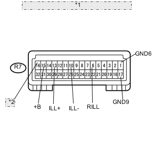
*1 Component with harness connected: (Map Light) *2 DOME Remove the map light with the connector connected.
-
Measure the voltage according to the value(s) in the table below.
Standard Voltage Tester Connection Switch Condition Specified Condition R7-6 (RILL) - R7-17 (GND9) Rear dome light off 11 to 14 V Rear dome light on Below 1 V R7-10 (ILL-) - R7-17 (GND9) Headlight dimmer switch off 11 to 14 V Headlight dimmer switch on Below 1 V R7-13 (ILL+) - R7-17 (GND9) Engine switch on (ACC) 11 to 14 V R7-15 (+B) - R7-17 (GND9) Always 11 to 14 V R7-16 (DOME) - R7-17 (GND9) Always 11 to 14 V -
Measure the resistance according to the value(s) in the table below.
Standard Resistance Tester Connection Condition Specified Condition R7-1 (GND6) - Body ground Always Below 1 Ω R7-17 (GND9) - Body ground Always Below 1 Ω If the result is not as specified, replace the map light assembly.
-