THEFT DETERRENT SYSTEM(w/ Entry and Start System) Theft Warning Siren Circuit
DESCRIPTION
The theft warning siren sounds if either of the following condition is met:
-
The theft deterrent system is in the alarm sounding state.
-
The theft warning siren is in the armed state when +B, GND or the communication line is open.
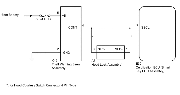
WIRING DIAGRAM
CAUTION / NOTICE / HINT
Note
-
When replacing the theft warning siren assembly, refer to the Service Bulletin.
-
Inspect the fuses for circuits related to this system before performing the following inspection procedure.
PROCEDURE
-
PERFORM ACTIVE TEST USING INTELLIGENT TESTER (THEFT WARNING SIREN)
-
Operate the intelligent tester according to the steps on the display and select "Active Test".
Entry&Start Tester Display Test Part Control Range Diagnostic Note Security Horn2 Theft warning siren ON / OFF - OK Siren operates normally.
OK 
REPLACE CERTIFICATION ECU (SMART KEY ECU ASSEMBLY)
NG 
-
-
CHECK HARNESS AND CONNECTOR (THEFT WARNING SIREN - BATTERY AND BODY GROUND)
-
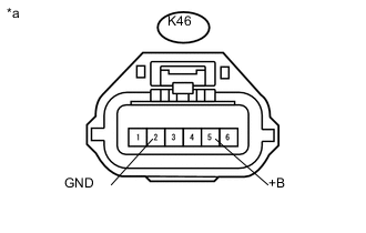
Text in Illustration *a Front view of wire harness connector
(to Theft Warning Siren Assembly)
Disconnect the K46 theft warning siren assembly connector.
-
Measure the voltage according to the value(s) in the table below.
Standard Voltage Tester Connection Condition Specified Condition K46-5 (+B) - Body ground Always 11 to 14 V -
Measure the resistance according to the value(s) in the table below.
Standard Resistance Tester Connection Condition Specified Condition K46-2 (GND) - Body ground Always Below 1 Ω
NG
REPAIR OR REPLACE HARNESS OR CONNECTOR
OK
-
-
CHECK HARNESS AND CONNECTOR (CERTIFICATION ECU [SMART KEY ECU ASSEMBLY] - THEFT WARNING SIREN)
-
Disconnect the E30 certification ECU (smart key ECU assembly) connector.
-
Disconnect the K46 theft warning siren assembly connector.
-
Measure the resistance according to the value(s) in the table below.
Standard Resistance Tester Connection Condition Specified Condition E30-7 (SSCL) - K46-4 (CONT) Always Below 1 Ω E30-7 (SSCL) - Body ground Always 10 kΩ or higher Result Result Proceed to OK A NG (except Hood Courtesy Switch Connector 4 Pin Type) B NG (for Hood Courtesy Switch Connector 4 Pin Type) C
B
REPAIR OR REPLACE HARNESS OR CONNECTOR
C 
CHECK HARNESS AND CONNECTOR (HOOD LOCK ASSEMBLY - CERTIFICATION ECU [SMART KEY ECU ASSEMBLY AND THEFT WARNING SIREN) Click here
A
-
-
CHECK THEFT WARNING SIREN (OPERATION)
-
Temporarily replace the theft warning siren assembly with a new or known good one (refer to the Service Bulletin).
-
Check that the theft warning siren operates normally.
OK Operates normally.
OK
END (THEFT WARNING SIREN ASSEMBLY IS DEFECTIVE)
NG
REPLACE CERTIFICATION ECU (SMART KEY ECU ASSEMBLY)
-
-
CHECK HARNESS AND CONNECTOR (HOOD LOCK ASSEMBLY - CERTIFICATION ECU [SMART KEY ECU ASSEMBLY AND THEFT WARNING SIREN)
-
Disconnect the E30 certification ECU (smart key ECU assembly) connector.
-
Disconnect the A8 hood lock assembly connector.
-
Disconnect the K46 theft warning siren assembly connector.
-
Measure the resistance according to the value(s) in the table below.
Standard Resistance Tester Connection Condition Specified Condition A8-1 (SLF+) - E30-7 (SSCL) Always Below 1 Ω A8-3 (SLF-) - K46-4 (CONT) Always Below 1 Ω A8-1 (SLF+) - Body ground Always 10 kΩ or higher A8-3 (SLF-) - Body ground Always 10 kΩ or higher
OK
REPLACE HOOD LOCK ASSEMBLY Click here
NG
REPAIR OR REPLACE HARNESS OR CONNECTOR
-