THEFT DETERRENT SYSTEM(w/ Entry and Start System) Intrusion Sensor Cancel Switch Circuit
DESCRIPTION
-
When the intrusion sensor cancel switch on the map light assembly is pressed, the sensor off signal is sent to the main body ECU (multiplex network body ECU) which causes the intrusion sensor to stop operating.
WIRING DIAGRAM
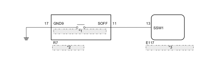
| *1 | Intrusion Sensor Cancel Switch |
| *2 | Map Light Assembly |
| *3 | Main Body ECU (Multiplex Network Body ECU) |
CAUTION / NOTICE / HINT
Note
-
If the main body ECU (multiplex network body ECU) is replaced, refer to the Service Bulletin.
-
w/ Door Control Battery:
As the door control battery is installed between the vehicle battery and main body ECU (multiplex network body ECU), first perform the inspections in On-Vehicle Inspection to confirm that there are no malfunctions in the power source circuit for the main body ECU (multiplex network body ECU) before performing this troubleshooting procedure. Click here
PROCEDURE
-
READ VALUE USING GTS (INTRUSION SENS OFF SW)
-
Connect the GTS to the DLC3.
-
Turn the engine switch on (IG).
-
Turn the GTS on.
-
Enter the following menus: Body Electrical / Main Body / Data List.
-
According to the display on the GTS, read the Data List.
Main Body Tester Display Measurement Item/Range Normal Condition Diagnostic Note Intrusion Sens OFF SW Intrusion sensor cancel switch/ON or OFF ON: Intrusion sensor cancel switch on
OFF: Intrusion sensor cancel switch off
- OK The indicator on the GTS switches between ON and OFF in accordance with the intrusion sensor cancel switch status.
OK 
PROCEED TO NEXT CIRCUIT INSPECTION SHOWN IN PROBLEM SYMPTOMS TABLE Click here
NG 
-
-
CHECK HARNESS AND CONNECTOR (MAIN BODY ECU [MULTIPLEX NETWORK BODY ECU] - MAP LIGHT ASSEMBLY AND BODY GROUND)
-
Disconnect the E117 main body ECU (multiplex network body ECU) connector.
-
Disconnect the R7 map light assembly connector.
-
Measure the resistance according to the value(s) in the table below.
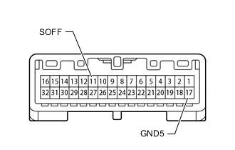
Standard Resistance Tester Connection Condition Specified Condition E117-13 (SSW1) - R7-11 (SOFF) Always Below 1 Ω R7-17 (GND9) - Boy ground Always Below 1 Ω E117-13 (SSW1) - Body ground Always 10 kΩ or higher R7-11 (SOFF) - Body ground Always 10 kΩ or higher
NG
REPAIR OR REPLACE HARNESS OR CONNECTOR
OK
-
-
INSPECT MAP LIGHT ASSEMBLY (INTRUSION SENSOR CANCEL SWITCH)
-
Remove the map light assembly (intrusion sensor cancel switch) Click here.
-
Measure the resistance according to the value(s) in the table below.
Standard Resistance Tester Connection Condition Specified Condition 11 (SOFF) - 17 (GND9) Intrusion sensor cancel switch not pressed 10 kΩ or higher 11 (SOFF) - 17 (GND9) Intrusion sensor cancel switch pressed Below 1 Ω Result Result Proceed to OK (for LHD) A OK (for RHD) B NG C
A
REPLACE MAIN BODY ECU [MULTIPLEX NETWORKBODY ECU] (MULTIPLEX NETWORK BODY ECU) Click here
B
REPLACE MAIN BODY ECU [MULTIPLEX NETWORKBODY ECU] Click here
C
REPLACE MAP LIGHT ASSEMBLY (INTRUSION SENSOR CANCEL SWITCH) Click here
-