THEFT DETERRENT SYSTEM(w/ Entry and Start System) Intrusion Sensor Cancel Switch Circuit
DESCRIPTION
-
When the intrusion sensor cancel switch on the map light is pressed, the sensor off signal is sent to the certification ECU (smart key ECU assembly) which causes the intrusion sensor to stop operating.
WIRING DIAGRAM
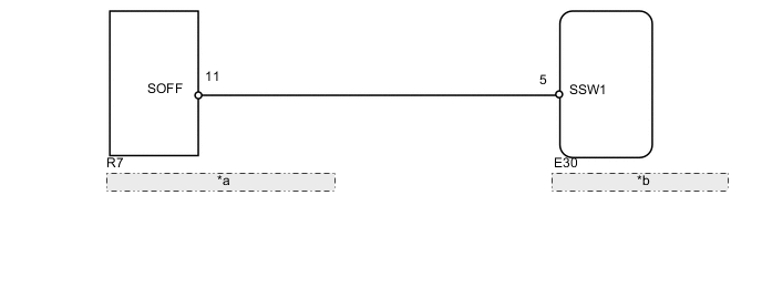
| *a | Map Light Assembly (Intrusion Sensor Cancel Switch) |
| *b | Certification ECU (Smart Key ECU Assembly) |
PROCEDURE
-
READ VALUE USING INTELLIGENT TESTER (INTRUSION SENSOR CANCEL SWITCH)
-
Using the intelligent tester, read the Data List.
Entry&Start Tester Display Measurement Item / Display (Range) Normal Condition Diagnostic Note Intrusion sensor OFF Intrusion sensor cancel switch /
ON or OFF
ON: Intrusion sensor active (switch off)
OFF: Intrusion sensor not active (switch on)
- OK ON (intrusion sensor active [switch off]) appears on screen.
OK 
REPLACE CERTIFICATION ECU (SMART KEY ECU ASSEMBLY)
NG 
-
-
CHECK HARNESS AND CONNECTOR (CERTIFICATION ECU [SMART KEY ECU ASSEMBLY] - MAP LIGHT ASSEMBLY)
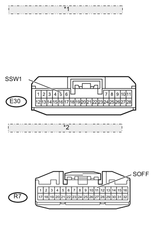
*1 Front view of wire harness connector: (to Certification ECU [Smart Key ECU Assembly]) *2 Front view of wire harness connector: (to Map Light)
-
Disconnect the E30 ECU connector.
-
Disconnect the R7 light connector.
-
Measure the resistance according to the value(s) in the table below.
Standard Resistance Tester Connection Condition Specified Condition E30-5 (SSW1) - R7-11 (SOFF) Always Below 1 Ω E30-5 (SSW1) or R7-11 (SOFF) - Body ground Always 10 kΩ or higher
NG
REPAIR OR REPLACE HARNESS OR CONNECTOR
OK
-
-
CHECK MAP LIGHT ASSEMBLY (INTRUSION SENSOR CANCEL SWITCH [OPERATION])
-
Temporarily replace the map light assembly (intrusion sensor cancel switch) with a new or normally functioning one Click here.
-
Turn the intrusion sensor off by pressing the intrusion sensor cancel switch. Check if the switch operates normally by checking that the theft deterrent system does not operate when you move your hand in front of the sensor.
OK Intrusion sensor cancel switch operates normally.
OK
END (MAP LIGHT [INTRUSION SENSOR CANCEL SWITCH] IS FAULTY)
NG
REPLACE CERTIFICATION ECU (SMART KEY ECU ASSEMBLY)
-