THEFT DETERRENT SYSTEM(w/ Entry and Start System) Engine Hood Courtesy Switch Circuit
DESCRIPTION
-
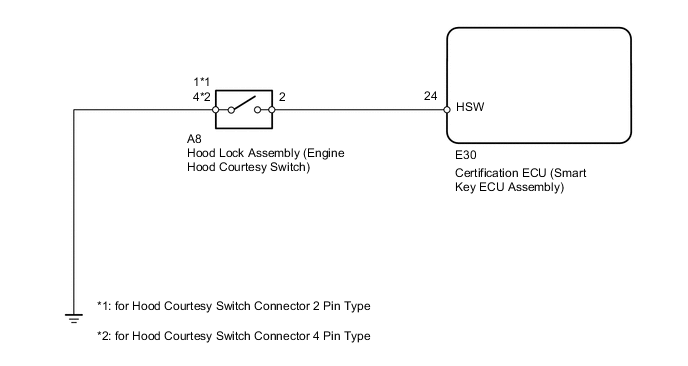
The engine hood courtesy switch is built into the hood lock. This switch turns on when the engine hood is opened and turns off when the engine hood is closed.
WIRING DIAGRAM
PROCEDURE
-
READ VALUE USING INTELLIGENT TESTER (ENGINE HOOD COURTESY SWITCH)
-
Using the intelligent tester, read the Data List.
Entry&Start Tester Display Measurement Item / Display (Range) Normal Condition Diagnostic Note Hood Courtesy Switch Engine hood courtesy switch /
ON or OFF
ON: Engine hood is open
OFF: Engine hood is closed
- OK ON (engine hood is open) appears on screen.
OK 
REPLACE CERTIFICATION ECU (SMART KEY ECU ASSEMBLY)
NG 
-
-
INSPECT HOOD LOCK ASSEMBLY (ENGINE HOOD COURTESY SWITCH)
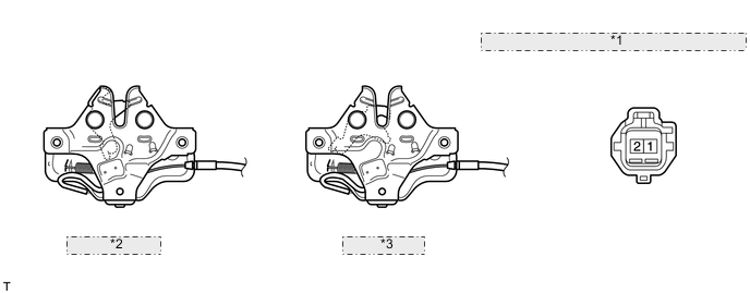
for Hood Courtesy Switch Connector 2 Pin Type (for LHD) *1 Component without harness connected: (Hood Lock Assembly) *2 Unlock Position *3 Lock Position
-
for Hood Courtesy Switch Connector 2 Pin Type (for LHD):
-
Remove the hood lock Click here.
-
Measure the resistance according to the value(s) in the table below.
Standard Resistance Tester Connection Condition Specified Condition 1 - 2 Unlock position 10 kΩ or higher 1 - 2 Lock position Below 1 Ω
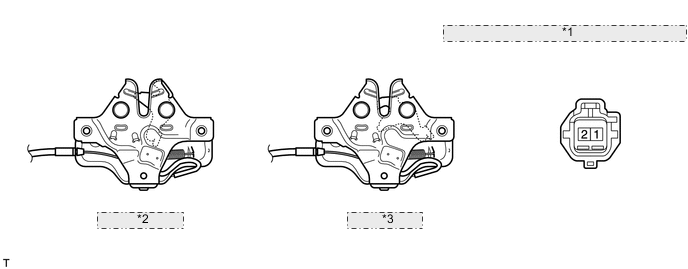
for Hood Courtesy Switch Connector 2 Pin Type (for RHD) *1 Component without harness connected: (Hood Lock Assembly) *2 Unlock Position *3 Lock Position -
-
for Hood Courtesy Switch Connector 2 Pin Type (for RHD):
-
Remove the hood lock Click here.
-
Measure the resistance according to the value(s) in the table below.
Standard Resistance Tester Connection Condition Specified Condition 1 - 2 Unlock position 10 kΩ or higher 1 - 2 Lock position Below 1 Ω
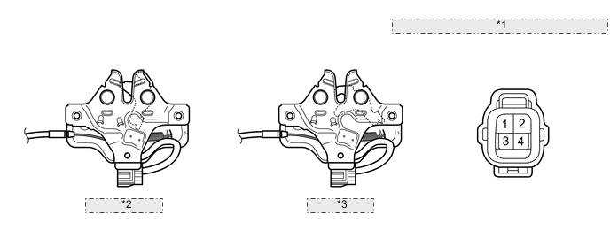
for Hood Courtesy Switch Connector 4 Pin Type *1 Component without harness connected: (Hood Lock Assembly) *2 Unlock Position *3 Lock Position -
-
for Hood Courtesy Switch Connector 4 Pin Type:
-
Remove the hood lock Click here.
-
Measure the resistance according to the value(s) in the table below.
Standard Resistance Tester Connection Condition Specified Condition 2 - 4 Unlock position 10 kΩ or higher 2 - 4 Lock position Below 1 Ω
-
NG
REPLACE HOOD LOCK ASSEMBLY (ENGINE HOOD COURTESY SWITCH)
OK
-
-
CHECK HARNESS AND CONNECTOR (CERTIFICATION ECU [SMART KEY ECU ASSEMBLY] - HOOD LOCK AND BODY GROUND)
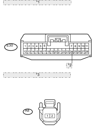
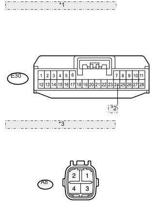
*1 Front view of wire harness connector: (to Certification ECU [Smart Key ECU Assembly]) *2 HSW *3 Front view of wire harness connector: (to Hood Lock)
-
*1 Front view of wire harness connector: (to Certification ECU [Smart Key ECU Assembly]) *2 HSW *3 Front view of wire harness connector: (to Hood Lock) for Hood Courtesy Switch Connector 2 Pin Type:
-
Disconnect the E30 ECU connector.
-
Disconnect the A8 switch connector.
-
Measure the resistance according to the value(s) in the table below.
Standard Resistance Tester Connection Condition Specified Condition E30-24 (HSW) - A8-2 Always Below 1 Ω A8-1 - Body ground Always Below 1 Ω E30-24 (HSW) or A8-2 - Body ground Always 10 kΩ or higher
-
-
for Hood Courtesy Switch Connector 4 Pin Type:
-
Disconnect the E30 ECU connector.
-
Disconnect the A8 switch connector.
-
Measure the resistance according to the value(s) in the table below.
Standard Resistance Tester Connection Condition Specified Condition E30-24 (HSW) - A8-2 Always Below 1 Ω A8-4 - Body ground Always Below 1 Ω E30-24 (HSW) or A8-2 - Body ground Always 10 kΩ or higher
-
OK
REPLACE CERTIFICATION ECU (SMART KEY ECU ASSEMBLY)
NG
REPAIR OR REPLACE HARNESS OR CONNECTOR
-