THEFT DETERRENT SYSTEM(w/ Entry and Start System) TERMINALS OF ECU
-
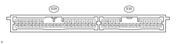
CHECK CERTIFICATION ECU (SMART KEY ECU ASSEMBLY)
-
Disconnect the E29 and E30 ECU connectors.
-
Measure the resistance and voltage according to the value(s) in the table below.
Terminal No. (Symbol) Wiring Color Terminal Description Condition Specified Condition E29-1 (+B) - Body ground B - Body ground +B power supply Always 11 to 14 V E29-18 (IG) - Body ground B - Body ground IG power supply Engine switch on (IG) 11 to 14 V Engine switch off Below 1 Ω E29-17 (E) - Body ground W-B - Body ground Ground Always Below 1 Ω
-
If the result is not as specified, there may be a malfunction on the wire harness side.
-
-
Reconnect the E29 and E30 ECU connectors.
-
Measure the resistance and voltage according to the value(s) in the table below.
Terminal No. (Symbol) Wiring Color Terminal Description Condition Specified Condition E29-2 (IND) - Body ground V - Body ground Security indicator signal Security indicator illuminates (illuminates only for 60 sec. in alarm sounding state (blinking when system in armed state)) 6 to 11 V E30-20 (SH-) - Body ground*1 LG - Body ground Security horn signal Security horn not sounding (theft deterrent system in alarm sounding state) 11 to 14 V Security horn sounding (theft deterrent system in alarm sounding state) 0.5 to 4 V E30-24 (HSW) - Body ground W - Body ground Engine hood courtesy switch signal Engine hood closed 10 kΩ or higher Engine hood open Below 1 Ω E30-7 (SSCL) - Body ground*2 L - Body ground Theft warning siren signal Theft warning siren sounding (theft warning system in alarm sounding state) Below 2 V Theft warning siren not sounding (theft warning system in alarm sounding state) 4.5 to 14 V E30-4 (IOUT) - Body ground*3 P - Body ground Intrusion sensor signal input No moving object detected 9 to 14 V Moving object detected during arming preparation state or armed state Pulse generation E30-5 (SSW1) - Body ground*3 Y - Body ground Intrusion sensor cancel switch signal Intrusion sensor cancel switch on Below 1.5 V Intrusion sensor cancel switch off 4.5 to 14 V E30-21 (CSIF) - Body ground*3 W - Body ground Tilt sensor signal input Vehicle tilt not detected 9 to 14 V Vehicle tilt detected during arming preparation state or armed state Pulse generation E30-23 (GBS) - Body ground*4 V - Body ground Glass breakage sensor signal Glass breakage sensor normal Below 2 V Glass breakage sensor malfunctioning 4.5 to 14 V Tech Tips
*1: w/ Security Horn
*2: w/ Theft Warning Siren
*3: w/ Intrusion Sensor
*4: w/ Glass Breakage Sensor
-
-
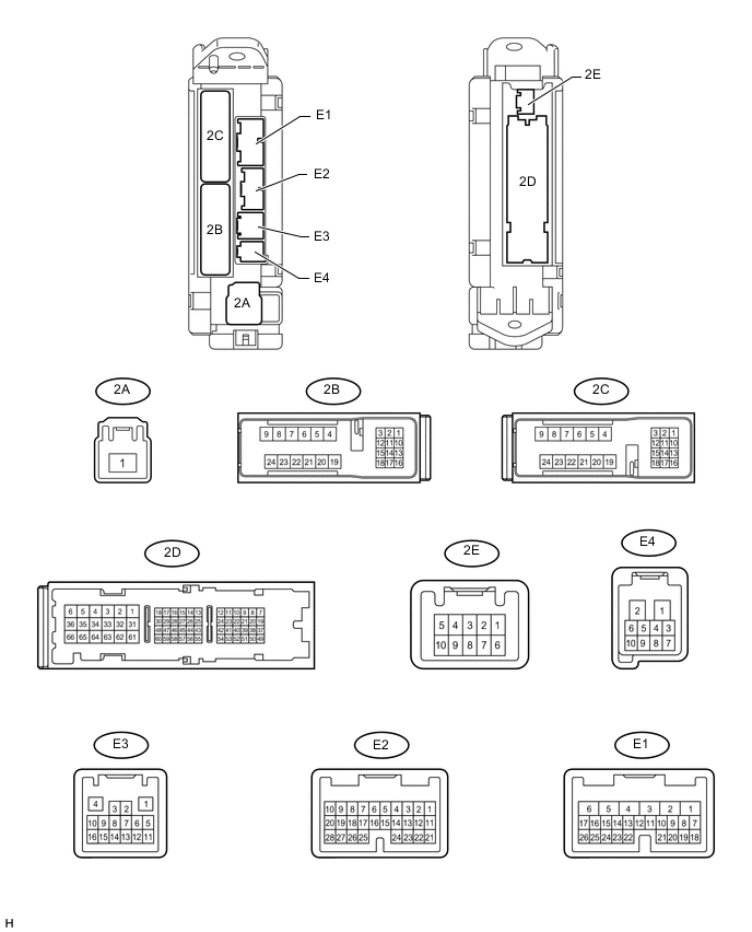
CHECK MAIN BODY ECU (COWL SIDE JUNCTION BLOCK LH)
-
Disconnect the 2A, 2B, 2D and E3 ECU connectors.
-
Measure the voltage and resistance according to the value(s) in the table below.
Terminal No. (Symbol) Wiring Color Terminal Description Condition Specified Condition 2A-1 (ALTB) - Body ground B - Body ground Battery power supply Always 11 to 14 V 2B-20 (BATB) - Body ground L - Body ground Battery power supply Always 11 to 14 V 2D-1 (IG) - Body ground G - Body ground IG power supply Engine switch on (IG) 11 to 14 V Engine switch off Below 1 V 2D-8 (ACC) - Body ground GR - Body ground ACC power supply Engine switch on (ACC) 11 to 14 V Engine switch off Below 1 V 2D-62 (GND2) - Body ground W-B - Body ground Ground Always Below 1 Ω E3-1 (GND3) - Body ground BR - Body ground Ground Always Below 1 Ω If the result is not as specified, there may be a malfunction in the wire harness.
-
Reconnect the 2A, 2B, 2D and E3 ECU connectors.
-
Measure the voltage of the connectors.
Terminal No. (Symbol) Wiring Color Terminal Description Condition Specified Condition E1-24 (DCTY) - Body ground L - Body ground*1
P - Body ground*2
Driver side door courtesy switch input Driver side door open Below 1 V Engine switch off, and driver side door courtesy switch off Pulse generation (see waveform 1 or 2) E2-21 (PCTY) - Body ground P - Body ground*1, *3
Y - Body ground*1, *4
L - Body ground*2
Front passenger side door courtesy switch input Front passenger side door open Below 1 V Engine switch off, and passenger side door courtesy switch off Pulse generation (see waveform 3 or 4) 2C-2 (LCTY) - Body ground W - Body ground Rear door LH courtesy light switch input Rear door LH open Below 1 V Engine switch off, and rear LH side door courtesy switch off Pulse generation (see waveform 5 or 6) E2-7 (RCTY) - Body ground G - Body ground Rear door RH courtesy light switch input Rear door RH open Below 1 V Engine switch off, and rear RH side door courtesy switch off Pulse generation (see waveform 7 or 8) E2-25 (BCTY) - Body ground W - Body ground Back door courtesy light switch input Back door open Below 1 V Engine switch off, and back door closed Pulse generation (see waveform 9 or 10) 2D-3 (ACT+) - Body ground L - Body ground Driver side door lock motor lock drive output Master switch (door control switch) or driver side door key cylinder off Below 1 V Master switch (door control switch) or driver side door key cylinder lock 11 to 14 V E1-5 (ACTD) - Body ground B - Body ground Driver side door lock motor unlock drive output Master switch (door control switch) or driver side door key cylinder off Below 1 V Master switch (door control switch) or driver side door key cylinder unlock 11 to 14 V 2D-3 (ACT+) - Body ground L - Body ground Front passenger side door lock motor lock drive output Master switch (door control switch) or driver side door key cylinder off Below 1 V Master switch (door control switch) or driver side door key cylinder lock 11 to 14 V 2D-2 (ACT-) - Body ground B - Body ground Front passenger side door lock motor unlock drive output Master switch (door control switch) or driver side door key cylinder off Below 1 V Master switch (door control switch) or driver side door key cylinder unlock 11 to 14 V 2D-3 (ACT+) - Body ground L - Body ground Rear door LH lock motor lock drive output Master switch (door control switch) or driver side door key cylinder off Below 1 V Master switch (door control switch) or driver side door key cylinder lock 11 to 14 V 2D-2 (ACT-) - Body ground B - Body ground Rear door LH lock motor unlock drive output Master switch (door control switch) or driver side door key cylinder off Below 1 V Master switch (door control switch) or driver side door key cylinder unlock 11 to 14 V 2D-3 (ACT+) - Body ground L - Body ground Rear door RH lock motor lock drive output Master switch (door control switch) or driver side door key cylinder off Below 1 V Master switch (door control switch) or driver side door key cylinder lock 11 to 14 V 2D-2 (ACT-) - Body ground B - Body ground Rear door RH lock motor unlock drive output Master switch (door control switch) or driver side door key cylinder off Below 1 V Master switch (door control switch) or driver side door key cylinder unlock 11 to 14 V E1-10 (UL3) - Body ground Y - Body ground*1
L - Body ground*2
Driver side door lock key switch input Driver side door key cylinder unlock Below 1 V Engine switch off, all doors closed and driver side door key cylinder neutral position Pulse generation (see waveform 11 or 12) 2D-53 (L2) - Body ground LG - Body ground Driver side door lock key switch input Driver side door key cylinder lock Below 1 V Engine switch off, all doors closed and driver side door key cylinder neutral position Pulse generation (see waveform 13 or 14) E1-9 (LSWD) - Body ground BE - Body ground*3
BR - Body ground*4
Driver side door lock position switch input Driver side door unlock Below 1 V Engine switch off, all doors closed and driver side door lock Pulse generation (see waveform 15 or 16) E2-27 (LSWP) - Body ground Y - Body ground*1
BE - Body ground*2
Passenger side door lock position switch input Passenger side door unlock Below 1 V Engine switch off, all doors closed and passenger side door lock Pulse generation (see waveform 17 or 18) 2C-1 (LSWL) - Body ground BE - Body ground*3
BR - Body ground*4
Rear door LH lock position switch input Rear door LH unlock Below 1 V Engine switch off, all doors closed and rear door LH lock Pulse generation (see waveform 19 or 20) E2-5 (LSWR) - Body ground BE - Body ground*3
BR - Body ground*4
Rear door RH lock position switch input Rear door RH unlock Below 1 V Engine switch off, all doors closed and rear door RH lock Pulse generation (see waveform 21 or 22) E1-26 (BDSU) - Body ground L - Body ground Back door opener switch input Back door lock opener switch off Below 1 V Back door lock opener switch on Pulse generation (see waveform 23 or 24) Tech Tips
-
*1: for LHD
-
*2: for RHD
-
*3: Model code except: GRJ200L-GNANKC, URJ202L-GNTEKC
-
*4: Model code: GRJ200L-GNANKC, URJ202L-GNTEKC
If the result is not as specified, the ECU may have a malfunction.
-
-
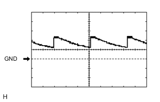
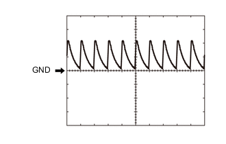
Using an oscilloscope, check waveform 1.
Waveform 1 (Reference) Item Content Terminal No. (Symbol) E1-24 (DCTY) - Body ground Tool Setting 5 V/DIV., 20 ms/DIV. Condition Engine switch off, and driver side door courtesy switch off -

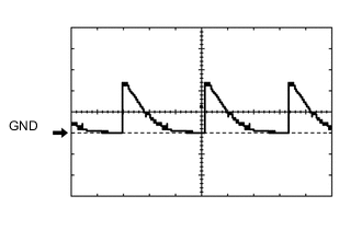
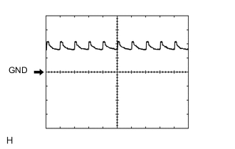
Using an oscilloscope, check waveform 2.
Waveform 2 (Reference) Item Content Terminal No. (Symbol) E1-24 (DCTY) - Body ground Tool Setting 5 V/DIV., 20 ms/DIV. Condition Engine switch off, and driver side door courtesy switch off -
Using an oscilloscope, check waveform 3.
Waveform 3 (Reference) Item Content Terminal No. (Symbol) E2-21 (PCTY) - Body ground Tool Setting 5 V/DIV., 20 ms/DIV. Condition Engine switch off, and passenger side door courtesy switch off -
Using an oscilloscope, check waveform 4.
Waveform 4 (Reference) Item Content Terminal No. (Symbol) E2-21 (PCTY) - Body ground Tool Setting 5 V/DIV., 20 ms/DIV. Condition Engine switch off, and passenger side door courtesy switch off -

Using an oscilloscope, check waveform 5.
Waveform 5 (Reference) Item Content Terminal No. (Symbol) 2C-2 (LCTY) - Body ground Tool Setting 5 V/DIV., 20 ms/DIV. Condition Engine switch off, and rear LH side door courtesy switch off -
Using an oscilloscope, check waveform 6.
Waveform 6 (Reference) Item Content Terminal No. (Symbol) 2C-2 (LCTY) - Body ground Tool Setting 5 V/DIV., 20 ms/DIV. Condition Engine switch off, and rear LH side door courtesy switch off -

Using an oscilloscope, check waveform 7.
Waveform 7 (Reference) Item Content Terminal No. (Symbol) E2-7 (RCTY) - Body ground Tool Setting 5 V/DIV., 20 ms/DIV. Condition Engine switch off, and rear RH side door courtesy switch off -

Using an oscilloscope, check waveform 8.
Waveform 8 (Reference) Item Content Terminal No. (Symbol) E2-7 (RCTY) - Body ground Tool Setting 5 V/DIV., 20 ms/DIV. Condition Engine switch off, and rear RH side door courtesy switch off -

Using an oscilloscope, check waveform 9.
Waveform 9 (Reference) Item Content Terminal No. (Symbol) E2-25 (BCTY) - Body ground Tool Setting 5 V/DIV., 20 ms/DIV. Condition Engine switch off, and back door closed -
Using an oscilloscope, check waveform 10.
Waveform 10 (Reference) Item Content Terminal No. (Symbol) E2-25 (BCTY) - Body ground Tool Setting 5 V/DIV., 20 ms/DIV. Condition Engine switch off, and back door closed -
Using an oscilloscope, check waveform 11.
Waveform 11 (Reference) Item Content Terminal No. (Symbol) E1-10 (UL3) - Body ground Tool Setting 5 V/DIV., 20 ms/DIV. Condition Engine switch off, all doors closed and driver side door key cylinder neutral position -
Using an oscilloscope, check waveform 12.
Waveform 12 (Reference) Item Content Terminal No. (Symbol) E1-10 (UL3) - Body ground Tool Setting 5 V/DIV., 20 ms/DIV. Condition Engine switch off, all doors closed and driver side door key cylinder neutral position -
Using an oscilloscope, check waveform 13.
Waveform 13 (Reference) Item Content Terminal No. (Symbol) 2D-53 (L2) - Body ground Tool Setting 5 V/DIV., 20 ms/DIV. Condition Engine switch off, all doors closed and driver side door key cylinder neutral position -
Using an oscilloscope, check waveform 14.
Waveform 14 (Reference) Item Content Terminal No. (Symbol) 2D-53 (L2) - Body ground Tool Setting 5 V/DIV., 20 ms/DIV. Condition Engine switch off, all doors closed and driver side door key cylinder neutral position -
Using an oscilloscope, check waveform 15.
Waveform 15 (Reference) Item Content Terminal No. (Symbol) E1-9 (LSWD) - Body ground Tool Setting 5 V/DIV., 20 ms/DIV. Condition Engine switch off, all doors closed and driver side door lock -
Using an oscilloscope, check waveform 16.
Waveform 16 (Reference) Item Content Terminal No. (Symbol) E1-9 (LSWD) - Body ground Tool Setting 5 V/DIV., 20 ms/DIV. Condition Engine switch off, all doors closed and driver side door lock -

Using an oscilloscope, check waveform 17.
Waveform 17 (Reference) Item Content Terminal No. (Symbol) E2-27 (LSWP) - Body ground Tool Setting 5 V/DIV., 20 ms/DIV. Condition Engine switch off, all doors closed and passenger side door lock -
Using an oscilloscope, check waveform 18.
Waveform 18 (Reference) Item Content Terminal No. (Symbol) E2-27 (LSWP) - Body ground Tool Setting 5 V/DIV., 20 ms/DIV. Condition Engine switch off, all doors closed and passenger side door lock -
Using an oscilloscope, check waveform 19.
Waveform 19 (Reference) Item Content Terminal No. (Symbol) 2C-1 (LSWL) - Body ground Tool Setting 5 V/DIV., 20 ms/DIV. Condition Engine switch off, all doors closed and rear door LH lock -
Using an oscilloscope, check waveform 20.
Waveform 20 (Reference) Item Content Terminal No. (Symbol) 2C-1 (LSWL) - Body ground Tool Setting 5 V/DIV., 20 ms/DIV. Condition Engine switch off, all doors closed and rear door LH lock -
Using an oscilloscope, check waveform 21.
Waveform 21 (Reference) Item Content Terminal No. (Symbol) E2-5 (LSWR) - Body ground Tool Setting 5 V/DIV., 20 ms/DIV. Condition Engine switch off, all doors closed and rear door RH lock -
Using an oscilloscope, check waveform 22.
Waveform 22 (Reference) Item Content Terminal No. (Symbol) E2-5 (LSWR) - Body ground Tool Setting 5 V/DIV., 20 ms/DIV. Condition Engine switch off, all doors closed and rear door RH lock -
Using an oscilloscope, check waveform 23.
Waveform 23 (Reference) Item Content Terminal No. (Symbol) E1-26 (BDSU) - Body ground Tool Setting 5 V/DIV., 20 ms/DIV. Condition Engine switch off, all doors closed and back door opener switch on -
Using an oscilloscope, check waveform 24.
Waveform 24 (Reference) Item Content Terminal No. (Symbol) E1-26 (BDSU) - Body ground Tool Setting 5 V/DIV., 20 ms/DIV. Condition Engine switch off, all doors closed and back door opener switch on
-