ENGINE IMMOBILISER SYSTEM(w/o Entry and Start System) Engine does not Start because No Initial Combustion
DESCRIPTION
-
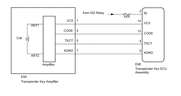
When the key is inserted into the ignition key cylinder, the antenna coil receives the key code. Then the amplifier amplifies the ID code and outputs it to the transponder key ECU assembly.
-
If this symptom occurs, there may be a communication problem between the transponder key amplifier and the transponder key ECU assembly.
WIRING DIAGRAM
CAUTION / NOTICE / HINT
Note
-
When replacing the key and transponder key ECU assembly, refer to the Service Bulletin.
-
Inspect the fuses for circuits related to this system before performing the following inspection procedure.
PROCEDURE
-
CLEAR DTC
-
Clear the DTCs Click here.
NEXT 
-
-
CHECK FOR DTC
-
Check for DTCs Click here.
Tech Tips
Before checking for DTCs, perform the "DTC Output Confirmation Operation" procedure.
Result Result Proceed to No DTC output A DTC output B
B 
GO TO DIAGNOSTIC TROUBLE CODE CHART Click here
A
-
-
CONFIRM ENGINE MODELS
-
Check the vehicle specifications.
Result Result Proceed to for 1GR-FE A for 1VD-FTV B
B 
READ VALUE USING INTELLIGENT TESTER (IMMOBILISER) Click here
A
-
-
READ VALUE USING INTELLIGENT TESTER (IMMOBILISER FUEL CUT)
-
Turn the ignition switch off.
-
Connect the intelligent tester to the DLC3.
-
Turn the ignition switch to ON.
-
Turn the intelligent tester on.
-
Enter the following menus: Powertrain / Engine and ECT / Data List.
Engine and ECT Tester Display Measurement Item/Range Normal Condition Stored as Freeze Frame Data Immobiliser Fuel Cut Status of immobiliser fuel cut/
ON or OFF
- Yes OK The item in the Data List indicates "OFF".
OK
GO TO SFI SYSTEM Click here
NG
-
-
READ VALUE USING INTELLIGENT TESTER (IMMOBILISER)
-
Turn the ignition switch off.
-
Connect the intelligent tester to the DLC3.
-
Turn the ignition switch to ON.
-
Turn the intelligent tester on.
-
Enter the following menus: Body / Immobiliser / Data List.
Immobiliser Tester Display Measurement Item/Range Normal Condition Diagnostic Note Immobiliser Engine immobiliser system status determined by transponder key ECU assembly /
Set or Unset
Set: Engine immobiliser set (engine start prohibited (no key in ignition key cylinder))
Unset: Engine immobiliser unset (engine start permitted (key inserted in ignition key cylinder))
When the engine immobiliser system does not change to the unset state, this item can be used to determine if the cause is the transponder key ECU assembly. OK On the intelligent tester screen, the display changes between Set and Unset as shown in the table above.
OK
GO TO ENGINE DOES NOT START BUT INITIAL COMBUSTION OCCURS Click here
NG
-
-
READ VALUE USING INTELLIGENT TESTER (IMMOBILISER)
-
Perform inspection using a different key that has been registered to the vehicle.
-
Turn the ignition switch off.
-
Connect the intelligent tester to the DLC3.
-
Turn the ignition switch to ON.
-
Turn the intelligent tester on.
-
Enter the following menus: Body / Immobiliser / Data List.
Immobiliser Tester Display Measurement Item/Range Normal Condition Diagnostic Note Immobiliser Engine immobiliser system status determined by transponder key ECU assembly /
Set or Unset
Set: Engine immobiliser set (engine start prohibited (no key in ignition key cylinder))
Unset: Engine immobiliser unset (engine start permitted (key inserted in ignition key cylinder))
When the engine immobiliser system does not change to the unset state, this item can be used to determine if the cause is the transponder key ECU assembly. OK On the intelligent tester screen, the display changes between Set and Unset as shown in the table above.
NG
CHECK TRANSPONDER KEY AMPLIFIER (VC5 SIGNAL) Click here
OK
-
-
CHECK WHETHER ENGINE STARTS WITH OTHER KEYS
-
Perform inspection using a different key that has been registered to the vehicle.
-
Turn the ignition switch to ON, wait for 5 seconds, and then attempt to start the engine.
Result Result Proceed to Engine cannot be started A Engine can be started B
A
GO TO ENGINE DOES NOT START BUT INITIAL COMBUSTION OCCURS Click here
B
REPLACE KEY Click here
-
-
CHECK TRANSPONDER KEY AMPLIFIER (VC5 SIGNAL)
-
Disconnect the E95 transponder key amplifier connector.
-
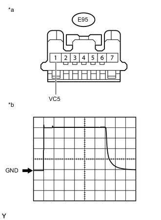
Text in Illustration *a Front view of wire harness connector
(to Transponder Key Amplifier)
*b Waveform Using an oscilloscope, check the waveform.
-
Waveform (Reference)
Measurement Condition Item Content Tester Connection E95-1 (VC5) - Body ground Tool Setting 1 V/DIV., 20 ms./DIV. Condition Key inserted in ignition key cylinder OK Waveform is output normally (refer to illustration).
-
OK
REPLACE TRANSPONDER KEY ECU ASSEMBLY
NG
-
-
CHECK HARNESS AND CONNECTOR (TRANSPONDER KEY AMPLIFIER - TRANSPONDER KEY ECU ASSEMBLY, IG TERMINAL VOLTAGE)
-
Disconnect the E95 transponder key amplifier connector.
-
Disconnect the E96 transponder key ECU assembly connector.
-
Measure the resistance according to the value(s) in the table below.
Standard Resistance Tester Connection Condition Specified Condition E95-1 (VC5) - E96-14 (VC5) Always Below 1 Ω E95-7 (AGND) - E96-5 (AGND) Always Below 1 Ω E95-1 (VC5) - Body ground Always 10 kΩ or higher -
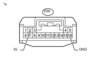
Text in Illustration *a Front view of wire harness connector
(to Transponder Key ECU Assembly)
Reconnect the transponder key amplifier connector.
-
Measure the voltage according to the value(s) in the table below.
Standard Voltage Tester Connection Switch Condition Specified Condition E96-2 (IG) - E96-16 (GND) Ignition switch ON 11 to 14 V
NG
REPAIR OR REPLACE HARNESS OR CONNECTOR
OK
-
-
CHECK TRANSPONDER KEY AMPLIFIER (TXCT SIGNAL)
-
Disconnect the E95 transponder key amplifier connector.
-
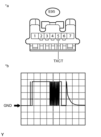
Text in Illustration *a Front view of wire harness connector
(to Transponder Key Amplifier)
*b Waveform Using an oscilloscope, check the waveform.
-
Waveform (Reference)
Measurement Condition Item Content Tester Connection E95-5 (TXCT) - Body ground Tool Setting 1 V/DIV., 20 ms./DIV. Condition Key inserted in ignition key cylinder OK Waveform is output normally (refer to illustration).
-
OK
REPLACE TRANSPONDER KEY ECU ASSEMBLY
NG
-
-
CHECK HARNESS AND CONNECTOR (TRANSPONDER KEY AMPLIFIER - TRANSPONDER KEY ECU ASSEMBLY)
-
Disconnect the E95 transponder key amplifier connector.
-
Disconnect the E96 transponder key ECU assembly connector.
-
Measure the resistance according to the value(s) in the table below.
Standard Resistance Tester Connection Condition Specified Condition E95-5 (TXCT) - E96-4 (TXCT) Always Below 1 Ω E95-5 (TXCT) - Body ground Always 10 kΩ or higher
NG
REPAIR OR REPLACE HARNESS OR CONNECTOR
OK
-
-
CHECK TRANSPONDER KEY AMPLIFIER (CODE SIGNAL)
-
Disconnect the E95 transponder key amplifier connector.
-
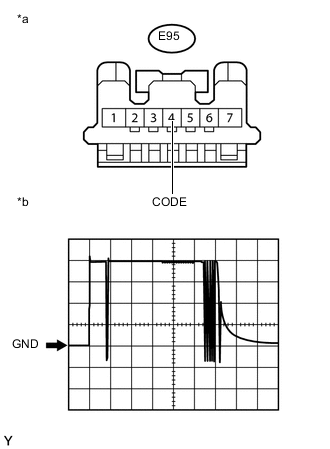
Text in Illustration *a Front view of wire harness connector
(to Transponder Key Amplifier)
*b Waveform Using an oscilloscope, check the waveform.
-
Waveform (Reference)
Measurement Condition Item Content Tester Connection E95-4 (CODE) - Body ground Tool Setting 1 V/DIV., 20 ms./DIV. Condition Key inserted in ignition key cylinder OK Waveform is output normally (refer to illustration).
-
OK
REPLACE TRANSPONDER KEY ECU ASSEMBLY
NG
-
-
CHECK HARNESS AND CONNECTOR (TRANSPONDER KEY AMPLIFIER - TRANSPONDER KEY ECU ASSEMBLY)
-
Disconnect the E95 transponder key amplifier connector.
-
Disconnect the E96 transponder key ECU assembly connector.
-
Measure the resistance according to the value(s) in the table below.
Standard Resistance Tester Connection Condition Specified Condition E95-4 (CODE) - E96-15 (CODE) Always Below 1 Ω E95-4 (CODE) - Body ground Always 10 kΩ or higher -
Reconnect the transponder key ECU assembly connector.
-
Reconnect the transponder key amplifier connector.
-

Text in Illustration *a Front view of wire harness connector
(to Transponder Key Amplifier)
*b Waveform Using an oscilloscope, check the waveform.
-
Waveform (Reference)
Measurement Condition Item Content Tester Connection E95-4 (CODE) - Body ground Tool Setting 1 V/DIV., 20 ms./DIV. Condition Key inserted in ignition key cylinder OK Waveform is output normally (refer to illustration). Result Result Proceed to Terminal CODE stuck high (5 V) A Terminal CODE stuck low (1 V or less) B Problem in wire harness or connector C
-
B
REPLACE TRANSPONDER KEY ECU ASSEMBLY Click here
C
REPAIR OR REPLACE HARNESS OR CONNECTOR
A
-
-
REPLACE TRANSPONDER KEY AMPLIFIER
-
Replace the transponder key amplifier Click here.
NEXT
-
-
CHECK WHETHER ENGINE STARTS
-
Check that the engine starts with an already registered vehicle key.
OK Engine starts normally.
OK
END (TRANSPONDER KEY AMPLIFIER WAS DEFECTIVE)
NG
-
-
REPLACE TRANSPONDER KEY ECU ASSEMBLY
-
Replace the transponder key ECU assembly.
NEXT
-
-
REGISTER KEY
-
Reregister the key (refer to the Service Bulletin).
NEXT
-
-
REGISTER ECU COMMUNICATION ID
-
Register the ECU communication ID (refer to the Service Bulletin).
NEXT
-
-
CHECK WHETHER ENGINE STARTS
-
Check that the engine starts with an already registered vehicle key.
OK Engine starts normally.
OK
END (TRANSPONDER KEY ECU ASSEMBLY WAS DEFECTIVE)
NG
-
-
REPLACE KEY
-
Replace the transponder key master transmitter with a new one (refer to the Service Bulletin).
NEXT
-
-
REREGISTER KEY
-
Reregister the key (refer to the Service Bulletin).
NEXT
-
-
CHECK WHETHER ENGINE STARTS
-
Check that the engine starts with an already registered vehicle key.
OK Engine starts normally. Result Result Proceed to OK A NG (for 1GR-FE) B NG (for 1VD-FTV) C
A
END (KEY (TRANSPONDER KEY MASTER TRANSMITTER) WAS DEFECTIVE)
B
GO TO SFI SYSTEM Click here
C
GO TO ECD SYSTEM Click here
-