KEY REMINDER WARNING SYSTEM TERMINALS OF ECU
-
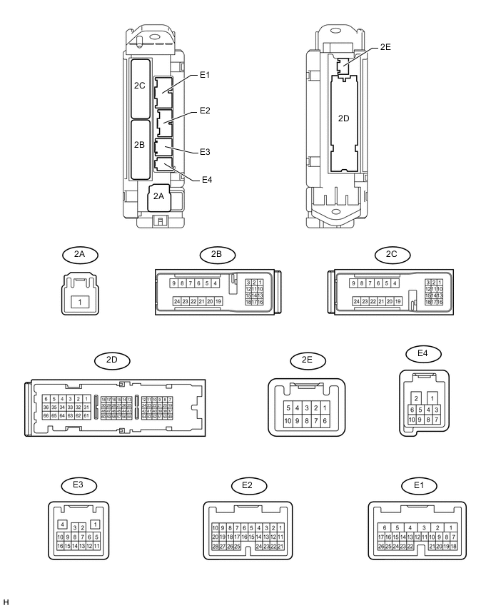
CHECK MAIN BODY ECU (COWL SIDE JUNCTION BLOCK LH)
-
Disconnect the 2A, 2B, 2D and E4 ECU connectors.
-
Measure the voltage and resistance according to the value(s) in the table below.
Terminal No. (Symbol) Wiring Color Terminal Description Condition Specified Condition 2B-20 (BATB) - Body ground L - Body ground Battery power supply Always 11 to 14 V 2A-1 (ACC) - Body ground B - Body ground ACC power supply Ignition switch ACC 11 to 14 V 2A-1 (ACC) - Body ground B - Body ground ACC power supply Ignition switch off Below 1 Ω 2D-62 (GND2) - Body ground W-B - Body ground Ground Always Below 1 Ω E4-5 (KSW) - Body ground BR - Body ground Unlock warning switch input No key in ignition key cylinder 10 kΩ or higher E4-5 (KSW) - Body ground BR - Body ground Unlock warning switch input Key inserted in ignition key cylinder Below 1 Ω If the result is not as specified, there may be a malfunction on the wire harness side.
-
Reconnect the 2A, 2B, 2D and E4 ECU connectors.
-
Measure the voltage according to the value(s) in the table below.
Terminal No. (Symbol) Wiring Color Terminal Description Condition Specified Condition E1-24 (DCTY) - Body ground L*1 - Body ground
Y*2 - Body ground
Driver side door courtesy switch input Driver side door open Below 1 V E1-24 (DCTY) - Body ground L*1 - Body ground
Y*2 - Body ground
Driver side door courtesy switch input Ignition switch off, and driver side door courtesy switch off Pulse generation Tech Tips
*1: for LHD
*2: for RHD
If the result is not as specified, the ECU may have a malfunction.
-