WIRELESS DOOR LOCK CONTROL SYSTEM(w/o Entry and Start System) TERMINALS OF ECU
-
CHECK MAIN BODY ECU
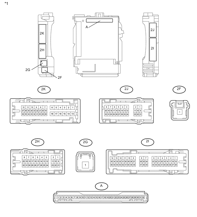
Text in Illustration *1 Cowl Side Junction Block LH - - 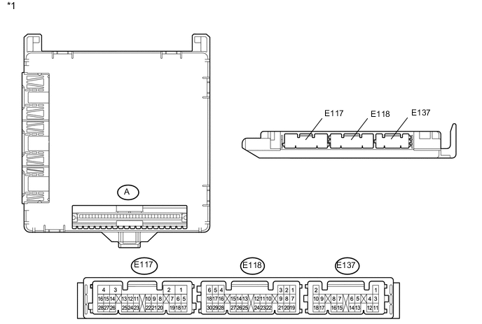
Text in Illustration *1 Main Body ECU - -
-
Remove the main body ECU from the cowl side junction block LH.
for LHD: Click here
for RHD: Click here
-
Connect the cowl side junction block LH connectors.
-
Measure the voltage and resistance according to the value(s) in the table below.
Terminal No. (Symbol) Wiring Color Terminal Description Condition Specified Condition A-11 (GND1) - Body ground None - Body ground Ground Always Below 1 Ω A-30 (ACC) - Body ground None - Body ground ACC power supply ignition switch ACC 11 to 14 V ignition switch off Below 1 V A-31 (BECU) - Body ground None - Body ground Battery power supply Always 11 to 14 V A-32 (IG) - Body ground None - Body ground IG power supply ignition switch ON 11 to 14 V ignition switch off Below 1 V If the result is not as specified, there may be a malfunction on the wire harness side.
-
Install the main body ECU to the cowl side junction block LH.
for LHD: Click here
for RHD: Click here
-
Measure the voltage according to the value(s) in the table below.
Terminal No. (Symbol) Wiring Color Terminal Description Condition Specified Condition 2H-29 (BZR) - Body ground G - Body ground Wireless door lock buzzer signal Wireless door lock buzzer off Below 1 V Wireless door lock buzzer on Pulse generation 2J-16 (LSFR) - Body ground B - Body ground Front door RH unlock detection switch input signal Front door RH unlocked Below 1 V ignition switch off, all doors closed and front door RH locked Pulse generation 2J-19 (LSFL) - Body ground G - Body ground Front door LH unlock detection switch input signal Front door LH unlocked Below 1 V ignition switch off, all doors closed and front door LH locked Pulse generation 2J-28 (KSW) - Body ground G - Body ground Key unlock warning switch input No key in ignition key cylinder Pulse generation Key in ignition key cylinder Below 1 V 2J-29 (RCTY) - Body ground BE - Body ground Rear door courtesy light switch assembly RH input signal Rear door RH open Below 1 V Rear door RH closed Pulse generation 2K-31 (BCTY) - Body ground W - Body ground Back door courtesy light switch input Back door closed Below 1 V Back door open Pulse generation 2K-33 (LSWL) - Body ground L - Body ground Rear door LH unlock detection switch input signal Rear door LH unlocked Below 1 V ignition switch off, all doors closed and rear door LH locked Pulse generation 2K-34 (LCTY) - Body ground BE - Body ground Rear door courtesy light switch assembly LH input signal Rear door LH open Below 1 V Rear door LH closed Pulse generation E117-2 (LSWR) - Body ground W - Body ground Rear door RH unlock detection switch input signal Rear door RH unlocked Below 1 V ignition switch off, all doors closed and rear door RH locked 11 to 14 V E118-4 (RDA) - Body ground G - Body ground Door control receiver input No key in ignition key cylinder, all doors closed and transmitter switch off → on Pulse generation E118-5 (PRG) - Body ground L - Body ground Door control receiver output Key in ignition key cylinder → No key in ignition key cylinder Pulse generation E118-6 (FLCY) - Body ground V - Body ground Front door courtesy light switch assembly LH input signal Front door LH open Below 1 V Front door LH closed Pulse generation E118-17 (LSWB) - Body ground B - Body ground Back door unlock detection switch input signal Back door unlocked Below 1 V ignition switch off, all doors closed and back door locked 11 to 14 V E118-27 (FRCY) - Body ground V - Body ground Front door courtesy light switch assembly RH input signal Front door RH open Below 1 V Front door RH closed Pulse generation If the result is not as specified, the ECU may have a malfunction.
-
-
CHECK DOOR CONTROL RECEIVER
-
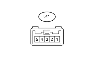
Disconnect the L47 receiver connector.
-
Measure the resistance and voltage according to the value(s) in the table below.
Terminal No. (Symbol) Wiring Color Terminal Description Condition Specified Condition L47-1 (GND) - Body ground BR - Body ground Ground Always Below 1 Ω L47-5 (+B) - Body ground R - Body ground Battery power supply Always 4.6 to 5.4 V
-
If the result is not as specified, there may be a malfunction on the wire harness side.
-
-