POWER DOOR LOCK CONTROL SYSTEM All Doors LOCK/UNLOCK Functions do not Operate Via Master Switch, Driver Side Door Key Cylinder
DESCRIPTION
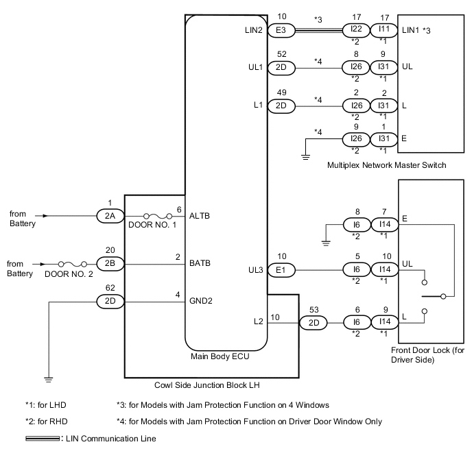
The main body ECU receives switch signals from the multiplex network master switch, and driver side door key cylinder switch signals from the front door lock. The main body ECU activates the door lock motor on each door according to these signals.
WIRING DIAGRAM
CAUTION / NOTICE / HINT
Note
Inspect the fuses for circuits related to this system before performing the following inspection procedure.
Tech Tips
Since the power door lock control system has functions that use LIN communication, first confirm that there is no malfunction in the communication system by inspecting the LIN communication functions in accordance with the "How to Proceed with Troubleshooting" procedures. Then, conduct the following inspection procedure.
PROCEDURE
-
CHECK DOOR LOCK OPERATION
Result Result Proceed to All doors cannot be locked through multiplex network master switch and driver side door key cylinder A All doors cannot be locked through multiplex network master switch (for Models with Jam Protection Function on Driver Door Window Only) B All doors cannot be locked through multiplex network master switch (for Models with Jam Protection Function on 4 Windows) C All doors cannot be locked through driver side door key cylinder D
B 
CHECK HARNESS AND CONNECTOR (MULTIPLEX NETWORK MASTER SWITCH - MAIN BODY ECU AND BODY GROUND) Click here
C
CHECK MULTIPLEX NETWORK MASTER SWITCH ASSEMBLY (OPERATION) Click here
D
READ VALUE USING INTELLIGENT TESTER (DOOR KEY LINKED LOCK AND UNLOCK SWITCH) Click here
A 
-
CHECK HARNESS AND CONNECTOR (MAIN BODY ECU - BATTERY AND BODY GROUND)
-
Disconnect the 2A, 2B and 2D main body ECU connectors.
-
Measure the voltage according to the value(s) in the table below.
Standard Voltage Tester Connection Condition Specified Condition 2A-1 (ALTB) - Body ground Always 11 to 14 V 2B-20 (BATB) - Body ground Always 11 to 14 V -
Measure the resistance according to the value(s) in the table below.
Standard Resistance Tester Connection Condition Specified Condition 2D-62 (GND2) - Body ground Always Below 1 Ω
OK 
REPLACE MAIN BODY ECU (COWL SIDE JUNCTION BLOCK LH)
NG
REPAIR OR REPLACE HARNESS OR CONNECTOR
-
-
CHECK HARNESS AND CONNECTOR (MULTIPLEX NETWORK MASTER SWITCH - MAIN BODY ECU AND BODY GROUND)
-
for LHD:
-
Disconnect the I31 master switch connector.
-
Disconnect the 2D main body ECU connector.
-
Measure the resistance according to the value(s) in the table below.
Standard Resistance Tester Connection Condition Specified Condition I31-9 (UL) - 2D-52 (UL1) Always Below 1 Ω I31-2 (L) - 2D-49 (L1) Always Below 1 Ω I31-1 (E) - Body ground Always Below 1 Ω I31-9 (UL) - Body ground Always 10 kΩ or higher I31-2 (L) - Body ground Always 10 kΩ or higher
-
-
for RHD:
-
Disconnect the I26 master switch connector.
-
Disconnect the 2D main body ECU connector.
-
Measure the resistance according to the value(s) in the table below.
Standard Resistance Tester Connection Condition Specified Condition I26-8 (UL) - 2D-52 (UL1) Always Below 1 Ω I26-2 (L) - 2D-49 (L1) Always Below 1 Ω I26-9 (E) - Body ground Always Below 1 Ω I26-8 (UL) - Body ground Always 10 kΩ or higher I26-2 (L) - Body ground Always 10 kΩ or higher
-
NG
REPAIR OR REPLACE HARNESS OR CONNECTOR
OK
-
-
CHECK MULTIPLEX NETWORK MASTER SWITCH ASSEMBLY (OPERATION)
-
Replace the multiplex network master switch with a normally functioning one Click here.
-
Check that all doors can be locked and unlocked by using the multiplex network master switch.
OK All doors can be locked and unlocked with multiplex network master switch.
OK
END (MULTIPLEX NETWORK MASTER SWITCH ASSEMBLY IS DEFECTIVE)
NG
REPLACE MAIN BODY ECU (COWL SIDE JUNCTION BLOCK LH)
-
-
READ VALUE USING INTELLIGENT TESTER (DOOR KEY LINKED LOCK AND UNLOCK SWITCH)
-
Use the Data List to check if the door key linked lock and unlock switches are functioning properly.
Main Body ECU Tester Display Measurement Item/Range Normal Condition Diagnostic Note Door Key Linked Lock SW Door key linked lock switch signal / ON or OFF ON: Driver side door key cylinder turned to lock position
OFF: Driver side door key cylinder not turned
- Door Key Linked Unlock SW Door key linked unlock switch signal / ON or OFF ON: Driver side door key cylinder turned to unlock position
OFF: Driver side door key cylinder not turned
- OK On tester screen, each item changes between ON and OFF according to above chart.
OK
REPLACE MAIN BODY ECU (COWL SIDE JUNCTION BLOCK LH)
NG
-
-
CHECK HARNESS AND CONNECTOR (FRONT DOOR LOCK - MAIN BODY ECU AND BODY GROUND)
-
for LHD:
-
Disconnect the I14 door lock connector.
-
Disconnect the E1 and 2D main body ECU connectors.
-
Measure the resistance according to the value(s) in the table below.
Standard Resistance Tester Connection Condition Specified Condition I14-10 (UL) - E1-10 (UL3) Always Below 1 Ω I14-9 (L) - 2D-53 (L2) Always Below 1 Ω I14-7 (E) - Body ground Always Below 1 Ω I14-10 (UL) - Body ground Always 10 kΩ or higher I14-9 (L) - Body ground Always 10 kΩ or higher
-
-
for RHD:
-
Disconnect the I6 door lock connector.
-
Disconnect the E1 and 2D main body ECU connectors.
-
Measure the resistance according to the value(s) in the table below.
Standard Resistance Tester Connection Condition Specified Condition I6-5 (UL) - E1-10 (UL3) Always Below 1 Ω I6-6 (L) - 2D-53 (L2) Always Below 1 Ω I6-8 (E) - Body ground Always Below 1 Ω I6-5 (UL) - Body ground Always 10 kΩ or higher I6-6 (L) - Body ground Always 10 kΩ or higher
-
NG
REPAIR OR REPLACE HARNESS OR CONNECTOR
OK
-
-
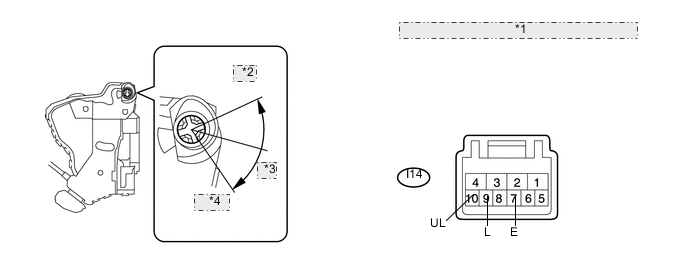
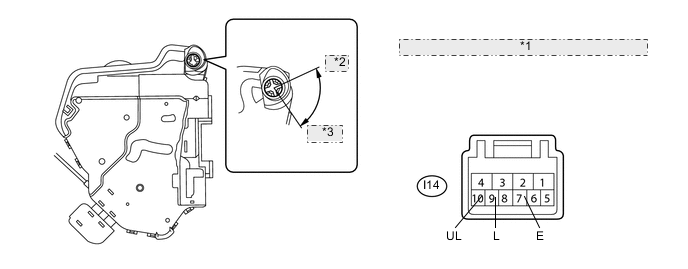
INSPECT FRONT DOOR LOCK ASSEMBLY (DOOR KEY LINKED LOCK AND UNLOCK SWITCH)
-
for LHD (w/o Double Locking Function):
*1 Component without harness connected: (Front Door Lock LH) *2 Lock *3 OFF *4 Unlock
-
Remove the front door lock LH Click here.
-
Measure the resistance according to the value(s) in the table below.
Standard Resistance Tester Connection Condition Specified Condition 9 (L) - 7 (E) Lock Below 1 Ω 9 (L) - 7 (E) Off 10 kΩ or higher 10 (UL) - 7 (E) Unlock Below 1 Ω 10 (UL) - 7 (E) Off 10 kΩ or higher
-
-
for LHD (w/ Double Locking Function):
*1 Component without harness connected: (Front Door Lock LH) *2 Lock *3 Unlock
-
Remove the front door lock LH Click here.
-
Measure the resistance according to the value(s) in the table below.
Standard Resistance Tester Connection Condition Specified Condition 9 (L) - 7 (E) Lock Below 1 Ω 9 (L) - 7 (E) Off 10 kΩ or higher 10 (UL) - 7 (E) Unlock Below 1 Ω 10 (UL) - 7 (E) Off 10 kΩ or higher
-
-
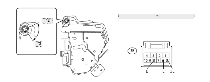
for RHD (w/o Double Locking Function):
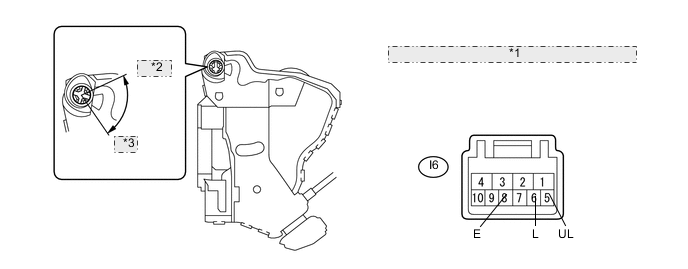
*1 Component without harness connected: (Front Door Lock RH) *2 Unlock *3 Lock
-
Remove the front door lock RH Click here.
-
Measure the resistance according to the value(s) in the table below.
Standard Resistance Tester Connection Condition Specified Condition 5 (UL) - 8 (E) Unlock Below 1 Ω 5 (UL) - 8 (E) Off 10 kΩ or higher 6 (L) - 8 (E) Lock Below 1 Ω 6 (L) - 8 (E) Off 10 kΩ or higher
-
-
for RHD (w/ Double Locking Function):
*1 Component without harness connected: (Front Door Lock RH) *2 Unlock *3 Lock
-
Remove the front door lock LH Click here.
-
Measure the resistance according to the value(s) in the table below.
Standard Resistance Tester Connection Condition Specified Condition 5 (UL) - 8 (E) Unlock Below 1 Ω 5 (UL) - 8 (E) Off 10 kΩ or higher 6 (L) - 8 (E) Lock Below 1 Ω 6 (L) - 8 (E) Off 10 kΩ or higher
-
OK
REPLACE MAIN BODY ECU (COWL SIDE JUNCTION BLOCK LH)
NG
REPLACE FRONT DOOR LOCK ASSEMBLY Click here
-