Click here
-

CHECK MULTIPLEX NETWORK MASTER SWITCH ASSEMBLY
-
for Models with Jam Protection Function on 4 Windows
-
Disconnect the I11*1 or I22*2 switch connector.
Tip:*1: for LHD
*2: for RHD
-
Measure the voltage and resistance according to the value(s) in the table below.
Terminal No. (Symbol) Wiring Color Terminal Description Condition Specified Condition I11-12 (GND) - Body ground*1 W-B - Body ground Ground Always Below 1 Ω I11-11 (B) - I11-12 (GND)*1 L - W-B Battery power supply Always 11 to 14 V I22-12 (GND) - Body ground*2 W-B - Body ground Ground Always Below 1 Ω I22-11 (B) - I22-12 (GND)*2 L - W-B Battery power supply Always 11 to 14 V Tip:*1: for LHD
*2: for RHD
If the result is not as specified, there may be a malfunction on the wire harness side.
-
-
for Models with Jam Protection Function on Driver Door Window Only
-
Disconnect the I31*1 or I26*2 switch connector.
Tip:*1: for LHD
*2: for RHD
-
Measure the voltage and resistance according to the value(s) in the table below.
Terminal No. (Symbol) Wiring Color Terminal Description Condition Specified Condition I31-1 (E) - Body ground*1 W-B - Body ground Ground Always Below 1 Ω I31-6 (B) - I31-1 (E)*1 L - W-B Battery power supply Always 11 to 14 V I26-9 (E) - Body ground*2 W-B - Body ground Ground Always Below 1 Ω I26-6 (B) - I26-9 (E)*2 L - W-B Battery power supply Always 11 to 14 V Tip:*1: for LHD
*2: for RHD
If the result is not as specified, there may be a malfunction on the wire harness side.
-
-
-
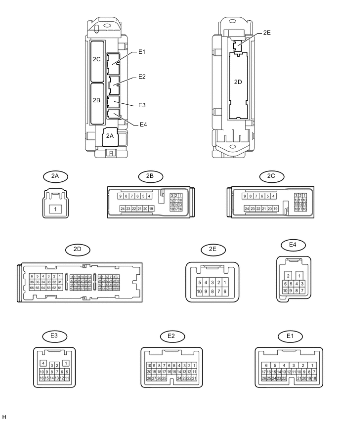
CHECK MAIN BODY ECU (COWL SIDE JUNCTION BLOCK LH)
-
Disconnect the 2A, 2B and 2D ECU connectors.
-
Measure the voltage and resistance according to the value(s) in the table below.
Terminal No. (Symbol) Wiring Color Terminal Description Condition Specified Condition 2B-20 (BATB) - Body ground L - Body ground Battery power supply Always 11 to 14 V 2A-1 (ACC) - Body ground B - Body ground ACC power supply Ignition switch ACC 11 to 14 V 2A-1 (ACC) - Body ground B - Body ground ACC power supply Ignition switch off Below 1 Ω 2D-62 (GND2) - Body ground W-B - Body ground Ground Always Below 1 Ω If the result is not as specified, there may be a malfunction on the wire harness side.
-
Reconnect the 2A, 2B and 2D ECU connectors.
-
Measure the voltage according to the value(s) in the table below.
Terminal No. (Symbol) Wiring Color Terminal Description Condition Specified Condition E1-24 (DCTY) - Body ground L*1 - Body ground
Y*2 - Body ground
Driver side door courtesy switch input Driver side door open Below 1 V E1-24 (DCTY) - Body ground L*1 - Body ground
Y*2 - Body ground
Driver side door courtesy switch input Ignition switch off, and driver side door courtesy switch off Pulse generation E2-21 (PCTY) - Body ground Y*1 - Body ground
L*2 - Body ground
Front passenger side door courtesy switch input Front passenger side door open Below 1 V E2-21 (PCTY) - Body ground Y*1 - Body ground
L*2 - Body ground
Front passenger side door courtesy switch input Ignition switch off, and passenger side door courtesy switch off Pulse generation 2C-2 (LCTY) - Body ground W - Body ground Rear door LH courtesy light switch input Rear door LH open Below 1 V 2C-2 (LCTY) - Body ground W - Body ground Rear door LH courtesy light switch input Ignition switch off, and rear LH side door courtesy switch off Pulse generation E2-7 (RCTY) - Body ground
*3
G - Body ground Rear door RH courtesy light switch input Rear door RH open Below 1 V E2-7 (RCTY) - Body ground
*3
G - Body ground Rear door RH courtesy light switch input Ignition switch off, and rear RH side door courtesy switch off Pulse generation E1-17 (RCTY) - Body ground
*4
G - Body ground Rear door RH courtesy light switch input Rear door RH open Below 1 V E1-17 (RCTY) - Body ground
*4
G - Body ground Rear door RH courtesy light switch input Ignition switch off, and rear RH side door courtesy switch off Pulse generation E2-25 (BCTY) - Body ground W - Body ground Back door courtesy light switch input Back door open Below 1 V E2-25 (BCTY) - Body ground W - Body ground Back door courtesy light switch input Ignition switch off, and back door closed Pulse generation 2D-3 (ACT+) - Body ground L - Body ground Door lock motor LOCK drive output Master switch (door control switch) or driver side door key cylinder in neutral position Below 1 V 2D-3 (ACT+) - Body ground L - Body ground Door lock motor LOCK drive output Master switch (door control switch) or driver side door key cylinder in lock position 11 to 14 V 2C-24 (ACT+) - Body ground L - Body ground Door lock motor LOCK drive output Master switch (door control switch) or driver side door key cylinder in neutral position Below 1 V 2C-24 (ACT+) - Body ground L - Body ground Door lock motor LOCK drive output Master switch (door control switch) or driver side door key cylinder in lock position 11 to 14 V E1-5 (ACTD) - Body ground B - Body ground Door lock motor UNLOCK drive output Master switch (door control switch) or driver side door key cylinder in neutral position Below 1 V E1-5 (ACTD) - Body ground B - Body ground Door lock motor UNLOCK drive output Master switch (door control switch) or driver side door key cylinder in unlock position 11 to 14 V 2D-2 (ACT-) - Body ground B - Body ground Door lock motor UNLOCK drive output Master switch (door control switch) or driver side door key cylinder in neutral position Below 1 V 2D-2 (ACT-) - Body ground B - Body ground Door lock motor UNLOCK drive output Master switch (door control switch) or driver side door key cylinder in unlock position 11 to 14 V 2C-23 (ACT-) - Body ground B - Body ground Door lock motor UNLOCK drive output Master switch (door control switch) or driver side door key cylinder in neutral position Below 1 V 2C-23 (ACT-) - Body ground B - Body ground Door lock motor UNLOCK drive output Master switch (door control switch) or driver side door key cylinder in unlock position 11 to 14 V E1-10 (UL3) - Body ground Y*1 - Body ground
L*2 - Body ground
Driver side door lock key switch input Driver side door key cylinder in unlock position Below 1 V E1-10 (UL3) - Body ground Y*1 - Body ground
L*2 - Body ground
Driver side door lock key switch input Ignition switch off, all doors closed and driver side door key cylinder in neutral position Pulse generation 2D-53 (L2) - Body ground LG - Body ground Driver side door lock key switch input Driver side door key cylinder in lock position Below 1 V 2D-53 (L2) - Body ground LG - Body ground Driver side door lock key switch input Ignition switch off, all doors closed and driver side door key cylinder in neutral position Pulse generation 2D-52 (UL1) - Body ground
*4
W - Body ground Master switch (door control switch) input Master switch (door control switch) in unlock position Below 1 V 2D-52 (UL1) - Body ground
*4
W - Body ground Master switch (door control switch) input Master switch (door control switch) in neutral position Pulse generation 2D-52 (UL1) - Body ground
*4
G - Body ground Door control switch assembly input Door control switch assembly in unlock position Below 1 V 2D-52 (UL1) - Body ground
*4
G - Body ground Door control switch assembly input Door control switch assembly in neutral position Pulse generation 2D-49 (L1) - Body ground
*4
BE - Body ground Master switch (door control switch) input Master switch (door control switch) in unlock position Below 1 V 2D-49 (L1) - Body ground
*4
BE - Body ground Master switch (door control switch) input Master switch (door control switch) in neutral position Pulse generation 2D-49 (L1) - Body ground
*4
R - Body ground Door control switch assembly input Door control switch assembly in unlock position Below 1 V 2D-49 (L1) - Body ground
*4
R - Body ground Door control switch assembly input Door control switch assembly in neutral position Pulse generation E1-1 (TR+) - Body ground
*3
L - Body ground Back door lock motor UNLOCK drive output Master switch (door control switch) or driver side door key cylinder in neutral position Below 1 V E1-1 (TR+) - Body ground
*3
L - Body ground Back door lock motor UNLOCK drive output Master switch (door control switch) or driver side door key cylinder in unlock position 11 to 14 V E1-9 (LSWD) - Body ground BR*5 - Body ground
BE*6 - Body ground
Driver side door lock position switch input Driver side door unlocked Below 1 V E1-9 (LSWD) - Body ground BR*5 - Body ground
BE*6 - Body ground
Driver side door lock position switch input Ignition switch off, all doors closed and driver side door locked Pulse generation E2-27 (LSWP) - Body ground Y*1 - Body ground
BR*2*5 - Body ground
BE*6 - Body ground
Front passenger side door lock position switch input Front passenger side door unlocked Below 1 V E2-27 (LSWP) - Body ground Y*1 - Body ground
BR*2*5 - Body ground
BE*6 - Body ground
Front passenger side door lock position switch input Ignition switch off, all doors closed and passenger side door locked Pulse generation 2C-1 (LSWL) - Body ground BR*5 - Body ground
BE*6 - Body ground
Rear door LH lock position switch input Rear door LH unlocked Below 1 V 2C-1 (LSWL) - Body ground BR*5 - Body ground
BE*6 - Body ground
Rear door LH lock position switch input Ignition switch off, all doors closed and rear door LH locked Pulse generation E2-5 (LSWR) - Body ground BR*5 - Body ground
BE*6 - Body ground
Rear door RH lock position switch input Rear door RH unlocked Below 1 V E2-5 (LSWR) - Body ground BR*5 - Body ground
BE*6 - Body ground
Rear door RH lock position switch input Ignition switch off, all doors closed and rear door RH locked Pulse generation E2-2 (LSWB) - Body ground
*4
LG - Body ground Back door lock position switch input Back door unlocked Below 1 V E2-2 (LSWB) - Body ground
*4
LG - Body ground Back door lock position switch input Ignition switch off, all doors closed and back door locked Pulse generation E1-26 (BDSU) - Body ground
*3
L - Body ground Back door opener switch input Back door lock opener switch off Below 1 V E1-26 (BDSU) - Body ground
*3
L - Body ground Back door opener switch input Back door lock opener switch on Pulse generation Tip:*1: for LHD
*2: for RHD
*3: w/ Entry and Start System
*4: w/o Entry and Start System
*5: for GRJ200L-GNANKC, URJ202L-GNTEKC
*6: except GRJ200L-GNANKC, URJ202L-GNTEKC
If the result is not as specified, the ECU may have a malfunction.
-
-

CHECK DOUBLE LOCK DOOR CONTROL RELAY (w/ Double Locking Function)
-
Disconnect the E86 double lock door control relay connector.
-
Measure the voltage according to the value(s) in the table below.
Terminal No. (Symbol) Wiring Color Terminal Description Condition Specified Condition E86-1 (+B) - E86-14 (GND) B - W-B Battery power supply Always 11 to 14 V E86-7 (CPUB) - E86-14 (GND) R - W-B ECU power supply Always 11 to 14 V E86-14 (GND) - Body ground W-B - Body ground Ground Always Below 1 V If the result is not as specified, there may be a malfunction on the wire harness side.
-
Reconnect the E86 double lock door control relay connector.
-
Measure the voltage and resistance according to the value(s) in the table below.
Terminal No. (Symbol) Wiring Color Terminal Description Condition Specified Condition E86-4 (ACTR) - E86-14 (GND) P - W-B All door double lock motor off signal Door lock set → unset Below 1 V → 11 to 14 V → Below 1 V E86-3 (ACTS) - E86-14 (GND) G - W-B All door double lock motor on signal Door lock unset → set Below 1 V → 11 to 14 V → Below 1 V E86-5 (DLPD) - E86-14 (GND) BR*1 - Body ground
BE*2 - Body ground
Double lock position switch signal Double lock set Below 1 Ω E86-5 (DLPD) - E86-14 (GND) BR*1 - Body ground
BE*2 - Body ground
Double lock position switch signal Double lock unset 10 kΩ or higher E86-6 (DLPP) - E86-14 (GND) GR - W-B Double lock position switch signal Double lock set Below 1 Ω E86-6 (DLPP) - E86-14 (GND) GR - W-B Double lock position switch signal Double lock unset 10 kΩ or higher E86-11 (DLPR) - E86-14 (GND) Y*1 - W-B
SB*2 - W-B
Double lock position switch signal Double lock set Below 1 Ω E86-11 (DLPR) - E86-14 (GND) Y*1 - W-B
SB*2 - W-B
Double lock position switch signal Double lock unset 10 kΩ or higher E86-12 (DLPL) - E86-14 (GND) LG - W-B Double lock position switch signal Double lock set Below 1 Ω E86-12 (DLPL) - E86-14 (GND) LG - W-B Double lock position switch signal Double lock unset 10 kΩ or higher Tip:*1: for GRJ200L-GNANKC, URJ202L-GNTEKC
*2: except GRJ200L-GNANKC, URJ202L-GNTEKC
If the result is not as specified, the ECU may have a malfunction.
-