NAVIGATION SYSTEM Reverse Signal Circuit
DESCRIPTION
The multi-media module receiver assembly receives a reverse signal from the park/neutral position switch assembly.
WIRING DIAGRAM
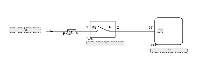
| *a | from IG1 NO.2 Relay |
| *b | REV |
| *c | Park/Neutral Position Switch Assembly |
| *d | Multi-media Module Receiver Assembly |
CAUTION / NOTICE / HINT
Note
Depending on the parts that are replaced during vehicle inspection or maintenance, performing initialization, registration or calibration may be needed. Refer to Precaution for Navigation System Click here.
PROCEDURE
-
CHECK VEHICLE SIGNAL (OPERATION CHECK)
-
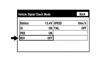
Enter the "Vehicle Signal Check Mode" screen. [Refer to check Vehicle Signal in Operation Check Click here].
-
Check that the display changes between ON and OFF according to the shift lever position.
OK Shift Lever Position Display R ON Except R OFF Tech Tips
This display is updated once per second. As a result, it is normal for the display to lag behind the actual shift lever position.
OK 
PROCEED TO NEXT SUSPECTED AREA SHOWN IN PROBLEM SYMPTOMS TABLE Click here
NG 
-
-
CHECK MULTI-MEDIA MODULE RECEIVER ASSEMBLY
-
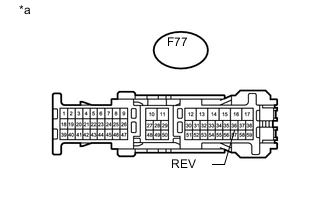
Text in Illustration *a Front view of wire harness connector
(to Multi-media Module Receiver Assembly)
Disconnect the multi-media module receiver assembly connector.
-
Measure the voltage according to the value(s) in the table below.
Standard Voltage Tester Connection Switch Condition Specified Condition F77-57 (REV) - Body ground Engine switch on (IG), shift lever in R 7.5 to 14 V F77-57 (REV) - Body ground Engine switch on (IG), shift lever not in R Below 1 V
OK
REPLACE MULTI-MEDIA MODULE RECEIVER ASSEMBLY Click here
NG
-
-
CHECK HARNESS AND CONNECTOR (MULTI-MEDIA MODULE RECEIVER ASSEMBLY - PARK/NEUTRAL POSITION SWITCH ASSEMBLY)
-
Disconnect the F77 multi-media module receiver assembly connector.
-
Disconnect the C24 park/neutral position switch assembly connector.
-
Measure the resistance according to the value(s) in the table below.
Standard Resistance Tester Connection Condition Specified Condition F77-57 (REV) - C24-2 (RL) Always Below 1 Ω F77-57 (REV) - Body ground Always 10 kΩ or higher
NG
REPAIR OR REPLACE HARNESS OR CONNECTOR
OK
-
-
CHECK HARNESS AND CONNECTOR (PARK/NEUTRAL POSITION SWITCH ASSEMBLY - BATTERY)
-
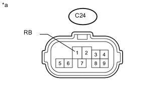
Text in Illustration *a Front view of wire harness connector
(to Park/neutral Position Switch Assembly)
Disconnect the park/neutral position switch assembly connector.
-
Measure the voltage according to the value(s) in the table below.
Standard Voltage Tester Connection Switch Condition Specified Condition C24-1 (RB) - Body ground Engine switch on (IG) 11 to 14 V Result Result Proceed to OK (for A750F) A OK (for AB60F) B OK (for AE80F) C NG D
A
REPLACE PARK/NEUTRAL POSITION SWITCH ASSEMBLY Click here
B
REPLACE PARK/NEUTRAL POSITION SWITCH ASSEMBLY Click here
C
REPLACE PARK/NEUTRAL POSITION SWITCH ASSEMBLY Click here
D
REPAIR OR REPLACE HARNESS OR CONNECTOR
-