NAVIGATION SYSTEM, Diagnostic DTC:B15C0, B15C1
| DTC Code | DTC Name |
|---|---|
| B15C0 | Short in GPS Antenna |
| B15C1 | Open in GPS Antenna |
DESCRIPTION
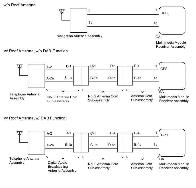
These DTCs are stored when a malfunction occurs in the navigation antenna assembly (w/o Roof Antenna) or telephone antenna assembly (w/ Roof Antenna).
| DTC Code | DTC Detection Condition | Trouble Area |
|---|---|---|
| B15C0 | Navigation antenna error |
|
| B15C1 | Error of the power source to the navigation antenna |
WIRING DIAGRAM
PROCEDURE
-
CHECK VEHICLE TYPE
-
Select the vehicle setting.
Result Result Proceed to w/o Roof Antenna A w/ Roof Antenna, w/o DAB Function B w/ Roof Antenna, w/ DAB Function C
B 
CHECK NO. 3 ANTENNA CORD SUB-ASSEMBLY Click here
C
CHECK DIGITAL AUDIO BROADCASTING ANTENNA ASSEMBLY Click here
A 
-
-
CHECK CONNECTION OF NAVIGATION ANTENNA ASSEMBLY
-
Check if the navigation antenna assembly is securely connected to the multi-media module receiver assembly.
OK Navigation antenna assembly is securely connected.
NG 
SECURELY CONNECT NAVIGATION ANTENNA ASSEMBLY
OK
-
-
REPLACE NAVIGATION ANTENNA ASSEMBLY
-
Replace the navigation antenna assembly with a normally functioning one Click here.
NEXT
-
-
CLEAR DTC
-
Clear the DTCs Click here.
NEXT
-
-
CHECK DTC
-
Recheck for DTCs and check if the same DTCs are output again Click here.
OK No DTCs are output.
OK
END (NAVIGATION ANTENNA ASSEMBLY IS DEFECTIVE)
NG
REPLACE MULTI-MEDIA MODULE RECEIVER ASSEMBLY Click here
-
-
CHECK NO. 3 ANTENNA CORD SUB-ASSEMBLY
-
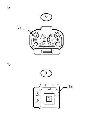
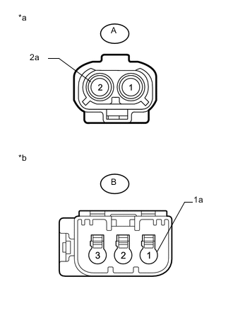
Text in Illustration *a Front view of wire harness connector
(to Telephone Antenna Assembly)
*b Front view of wire harness connector
(to No. 2 Antenna Cord Sub-assembly)
Disconnect the No. 3 antenna cord sub-assembly from telephone antenna assembly connector.
-
Disconnect the No. 3 antenna cord sub-assembly from No. 2 antenna cord sub-assembly.
-
Measure the resistance according to the value(s) in the table below.
Standard Resistance Tester Connection Condition Specified Condition A-2 - B-1 Always Below 1 Ω A-2a - B-1a Always Below 1 Ω A-2 - Body ground Always 10 kΩ or higher A-2a - Body ground Always 10 kΩ or higher
NG
REPLACE NO. 3 ANTENNA CORD SUB-ASSEMBLY Click here
OK
-
-
CHECK NO. 2 ANTENNA CORD SUB-ASSEMBLY
-
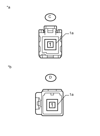
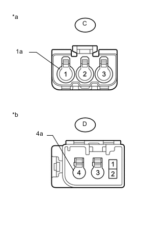
Text in Illustration *a Front view of wire harness connector
(to No. 3 Antenna Cord Sub-assembly)
*b Front view of wire harness connector
(to Antenna Cord Sub-assembly)
Disconnect the No. 2 antenna cord sub-assembly from No. 3 antenna cord sub-assembly.
-
Disconnect the No. 2 antenna cord sub-assembly from antenna cord sub-assembly.
-
Measure the resistance according to the value(s) in the table below.
Standard Resistance Tester Connection Condition Specified Condition C-1 - D-1 Always Below 1 Ω C-1a - D-1a Always Below 1 Ω C-1 - Body ground Always 10 kΩ or higher C-1a - Body ground Always 10 kΩ or higher
NG
REPLACE NO. 2 ANTENNA CORD SUB-ASSEMBLY Click here
OK
-
-
CHECK ANTENNA CORD SUB-ASSEMBLY
-
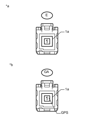
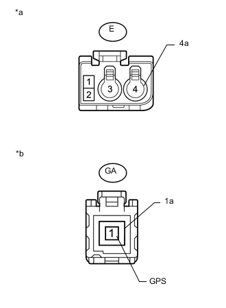
Text in Illustration *a Front view of wire harness connector
(to No. 2 Antenna Cord Sub-assembly)
*b Front view of wire harness connector
(to Multi-media Module Receiver Assembly)
Disconnect the antenna cord sub-assembly from No. 2 antenna cord sub-assembly.
-
Disconnect the antenna cord sub-assembly from multi-media module receiver assembly.
-
Measure the resistance according to the value(s) in the table below.
Standard Resistance Tester Connection Condition Specified Condition E-1 - GA-1 (GPS) Always Below 1 Ω E-1a - GA-1a Always Below 1 Ω E-1 - Body ground Always 10 kΩ or higher E-1a - Body ground Always 10 kΩ or higher
NG
REPLACE ANTENNA CORD SUB-ASSEMBLY Click here
OK
-
-
REPLACE TELEPHONE ANTENNA ASSEMBLY
-
Replace the telephone antenna assembly with a normally functioning one Click here.
NEXT
-
-
CLEAR DTC
-
Clear the DTCs Click here.
NEXT
-
-
CHECK DTC
-
Recheck for DTCs and check if the same DTCs are output again Click here.
OK No DTCs are output.
OK
END (TELEPHONE ANTENNA ASSEMBLY IS DEFECTIVE)
NG
REPLACE MULTI-MEDIA MODULE RECEIVER ASSEMBLY Click here
-
-
CHECK DIGITAL AUDIO BROADCASTING ANTENNA ASSEMBLY
-
Text in Illustration *a Front view of wire harness connector
(to Telephone Antenna Assembly)
*b Front view of wire harness connector
(to No. 2 Antenna Cord Sub-assembly)
Disconnect the digital audio broadcasting antenna assembly from telephone antenna assembly connector.
-
Disconnect the digital audio broadcasting antenna assembly from No. 2 antenna cord sub-assembly.
-
Measure the resistance according to the value(s) in the table below.
Standard Resistance Tester Connection Condition Specified Condition A-2 - B-1 Always Below 1 Ω A-2a - B-1a Always Below 1 Ω A-2 - Body ground Always 10 kΩ or higher A-2a - Body ground Always 10 kΩ or higher
NG
REPLACE DIGITAL AUDIO BROADCASTING ANTENNA ASSEMBLY Click here
OK
-
-
CHECK NO. 2 ANTENNA CORD SUB-ASSEMBLY
-
Text in Illustration *a Front view of wire harness connector
(to Digital Audio Broadcasting Antenna Assembly)
*b Front view of wire harness connector
(to Antenna Cord Sub-assembly)
Disconnect the No. 2 antenna cord sub-assembly from digital audio broadcasting antenna assembly.
-
Disconnect the No. 2 antenna cord sub-assembly from antenna cord sub-assembly.
-
Measure the resistance according to the value(s) in the table below.
Standard Resistance Tester Connection Condition Specified Condition C-1 - D-4 Always Below 1 Ω C-1a - D-4a Always Below 1 Ω C-1 - Body ground Always 10 kΩ or higher C-1a - Body ground Always 10 kΩ or higher
NG
REPLACE NO. 2 ANTENNA CORD SUB-ASSEMBLY Click here
OK
-
-
CHECK ANTENNA CORD SUB-ASSEMBLY
-
Text in Illustration *a Front view of wire harness connector
(to No. 2 Antenna Cord Sub-assembly)
*b Front view of wire harness connector
(to Multi-media Module Receiver Assembly)
Disconnect the antenna cord sub-assembly from No. 2 antenna cord sub-assembly.
-
Disconnect the antenna cord sub-assembly from multi-media module receiver assembly.
-
Measure the resistance according to the value(s) in the table below.
Standard Resistance Tester Connection Condition Specified Condition E-4 - GA-1 (GPS) Always Below 1 Ω E-4a - GA-1a Always Below 1 Ω E-4 - Body ground Always 10 kΩ or higher E-4a - Body ground Always 10 kΩ or higher
NG
REPLACE ANTENNA CORD SUB-ASSEMBLY Click here
OK
-
-
REPLACE TELEPHONE ANTENNA ASSEMBLY
-
Replace the telephone antenna assembly with a normally functioning one Click here.
NEXT
-
-
CLEAR DTC
-
Clear the DTCs Click here.
NEXT
-
-
CHECK DTC
-
Recheck for DTCs and check if the same DTCs are output again Click here.
OK No DTCs are output.
OK
CHECK CONNECTION OF NAVIGATION ANTENNA ASSEMBLY Click here
NG
REPLACE MULTI-MEDIA MODULE RECEIVER ASSEMBLY Click here
-