NAVIGATION SYSTEM, Diagnostic DTC:B15C0, B15C1
| DTC Code | DTC Name |
|---|---|
| B15C0 | GPS Antenna Connection Malfunction(short) |
| B15C1 | GPS Antenna Connection Malfunction(break) |
DESCRIPTION
These DTCs are stored when a malfunction occurs in the navigation antenna assembly*1 or telephone antenna assembly*2.
-
*1: w/o Heated Windshield Defroster System
-
*2: w/ Heated Windshield Defroster System
| DTC Code | DTC Detection Condition | Trouble Area |
|---|---|---|
| B15C0 | Navigation antenna error |
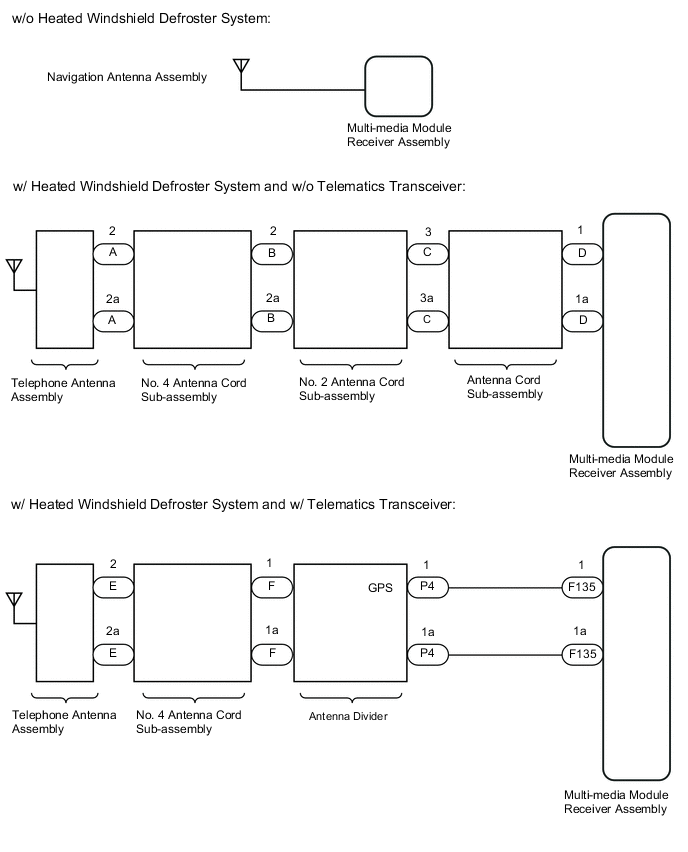
w/o Heated Windshield Defroster System:
w/ Heated Windshield Defroster System and w/o Telematics Transceiver:
w/ Heated Windshield Defroster System and w/ Telematics Transceiver: |
| B15C1 | Error of the power source to the navigation antenna |
WIRING DIAGRAM
CAUTION / NOTICE / HINT
Note
Depending on the parts that are replaced during vehicle inspection or maintenance, performing initialization, registration or calibration may be needed. Refer to Precaution for Navigation System.
PROCEDURE
-
CONFIRM MODEL
-
Choose the model to be inspected.
Result Result Proceed to w/o Heated Windshield Defroster System A w/ Heated Windshield Defroster System and w/o Telematics Transceiver B w/ Heated Windshield Defroster System and w/ Telematics Transceiver C
B 
INSPECT TELEPHONE ANTENNA ASSEMBLY Click here
C
INSPECT TELEPHONE ANTENNA ASSEMBLY Click here
A 
-
-
CHECK CONNECTION OF NAVIGATION ANTENNA ASSEMBLY
-
Check if the navigation antenna assembly is securely connected to the multi-media module receiver assembly.
OK Navigation antenna assembly is securely connected. Result Proceed to OK NG
NG 
SECURELY CONNECT NAVIGATION ANTENNA ASSEMBLY
OK
-
-
REPLACE NAVIGATION ANTENNA ASSEMBLY
-
Replace the navigation antenna assembly with a known good one.
Result Proceed to NEXT
NEXT
-
-
CLEAR DTC
-
Clear the DTCs.
Result Proceed to NEXT
NEXT
-
-
CHECK DTC
-
Recheck for DTCs and check if the same DTCs are output again.
OK No DTCs are output. Result Proceed to OK NG
OK
END (NAVIGATION ANTENNA ASSEMBLY IS DEFECTIVE)
NG
REPLACE MULTI-MEDIA MODULE RECEIVER ASSEMBLY Click here
-
-
INSPECT TELEPHONE ANTENNA ASSEMBLY
-
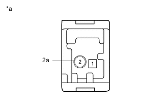
*a Telephone Antenna Assembly Remove the telephone antenna assembly.
-
Measure the resistance according to the value(s) in the table below.
Standard Resistance Tester Connection Condition Specified Condition 2 - 2a Always 4 to 11 kΩ Result Proceed to OK NG
NG
REPLACE TELEPHONE ANTENNA ASSEMBLY Click here
OK
-
-
INSPECT NO. 4 ANTENNA CORD SUB-ASSEMBLY
-
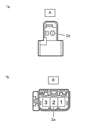
*a Front view of wire harness connector
(to Telephone Antenna Assembly)
*b Front view of wire harness connector
(to No. 2 Antenna Cord Sub-assembly)
Disconnect the No. 4 antenna cord sub-assembly from the telephone antenna assembly connector.
-
Disconnect the No. 4 antenna cord sub-assembly from the No. 2 antenna cord sub-assembly connector.
-
Measure the resistance according to the value(s) in the table below.
Standard Resistance Tester Connection Condition Specified Condition A-2 - B-2 Always Below 1 Ω A-2a - B-2a Always Below 1 Ω A-2 - Body ground Always 10 kΩ or higher A-2a - Body ground Always 10 kΩ or higher Result Proceed to OK NG
NG
REPLACE NO. 4 ANTENNA CORD SUB-ASSEMBLY Click here
OK
-
-
INSPECT NO. 2 ANTENNA CORD SUB-ASSEMBLY
-
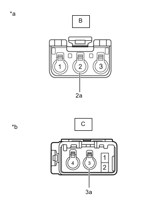
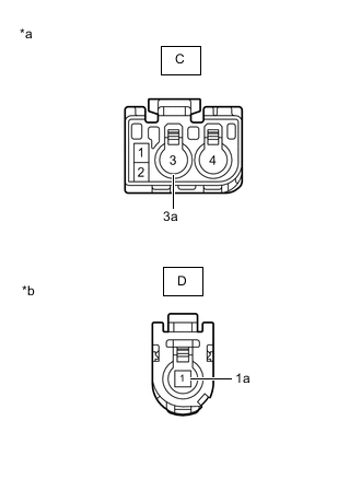
*a Front view of wire harness connector
(to No. 4 Antenna Cord Sub-assembly)
*b Front view of wire harness connector
(to Antenna Cord Sub-assembly)
Disconnect the No. 2 antenna cord sub-assembly from the No. 4 antenna cord sub-assembly connector.
-
Disconnect the No. 2 antenna cord sub-assembly from the antenna cord sub-assembly connector.
-
Measure the resistance according to the value(s) in the table below.
Standard Resistance Tester Connection Condition Specified Condition B-2 - C-3 Always Below 1 Ω B-2a - C-3a Always Below 1 Ω B-2 - Body ground Always 10 kΩ or higher B-2a - Body ground Always 10 kΩ or higher Result Proceed to OK NG
NG
REPLACE NO. 2 ANTENNA CORD SUB-ASSEMBLY Click here
OK
-
-
INSPECT ANTENNA CORD SUB-ASSEMBLY
-
*a Front view of wire harness connector
(to No. 2 Antenna Cord Sub-assembly)
*b Front view of wire harness connector
(to Multi-media Module Receiver Assembly)
Disconnect the antenna cord sub-assembly from the No. 2 antenna cord sub-assembly connector.
-
Disconnect the antenna cord sub-assembly from the multi-media module receiver assembly connector.
-
Measure the resistance according to the value(s) in the table below.
Standard Resistance Tester Connection Condition Specified Condition C-3 - D-1 Always Below 1 Ω C-3a - D-1a Always Below 1 Ω C-3a - Body ground Always 10 kΩ or higher C-3a - Body ground Always 10 kΩ or higher Result Proceed to OK NG
NG
REPLACE ANTENNA CORD SUB-ASSEMBLY Click here
OK
-
-
REPLACE TELEPHONE ANTENNA ASSEMBLY
-
Replace the telephone antenna assembly with a new or known good one.
Result Proceed to NEXT
NEXT
-
-
CLEAR DTC
-
Clear the DTCs.
Result Proceed to NEXT
NEXT
-
-
CHECK DTC
-
Recheck for DTCs and check if the same DTCs are output again.
OK No DTCs are output. Result Proceed to OK NG
OK
END (TELEPHONE ANTENNA ASSEMBLY IS DEFECTIVE)
NG
REPLACE MULTI-MEDIA MODULE RECEIVER ASSEMBLY Click here
-
-
INSPECT TELEPHONE ANTENNA ASSEMBLY
-
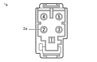
*a Telephone Antenna Assembly Remove the telephone antenna assembly.
-
Measure the resistance according to the value(s) in the table below.
Standard Resistance Tester Connection Condition Specified Condition 2 - 2a Always 4 to 11 kΩ Result Proceed to OK NG
NG
REPLACE TELEPHONE ANTENNA ASSEMBLY Click here
OK
-
-
INSPECT NO. 4 ANTENNA CORD SUB-ASSEMBLY
-
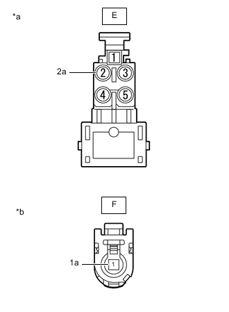
*a Front view of wire harness connector
(to Telephone Antenna Assembly)
*b Front view of wire harness connector
(to Antenna Divider)
Disconnect the No. 4 antenna cord sub-assembly from the telephone antenna assembly connector.
-
Disconnect the No. 4 antenna cord sub-assembly from the antenna divider connector.
-
Measure the resistance according to the value(s) in the table below.
Standard Resistance Tester Connection Condition Specified Condition E-2 - F-1 Always Below 1 Ω E-2a - F-1a Always Below 1 Ω E-2 - Body ground Always 10 kΩ or higher E-2a - Body ground Always 10 kΩ or higher Result Proceed to OK NG
NG
REPLACE NO. 4 ANTENNA CORD SUB-ASSEMBLY Click here
OK
-
-
INSPECT ANTENNA DIVIDER
-
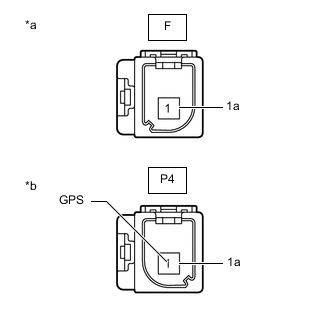
*a Front view of wire harness connector
(to No. 4 Antenna Cord Sub-assembly)
*b Front view of wire harness connector
(to Vehicle Wire Harness)
Disconnect the antenna divider from the No. 4 antenna cord sub-assembly connector.
-
Disconnect the antenna divider from the vehicle wire harness connector.
-
Measure the resistance according to the value(s) in the table below.
Standard Resistance Tester Connection Condition Specified Condition F-1 - P4-1 (GPS) Always 10 kΩ or higher F-1 - F-1a Always 10 kΩ or higher P4-1 (GPS) - P4-1a Always 243 to 267 Ω F-1 or P4-1 - Body ground Always 10 kΩ or higher F-1a or P4-1a - Body ground Always 10 kΩ or higher Result Proceed to OK NG
NG
REPLACE ANTENNA DIVIDER Click here
OK
-
-
CHECK HARNESS AND CONNECTOR (ANTENNA DIVIDER - MULTI-MEDIA MODULE RECEIVER ASSEMBLY)
-
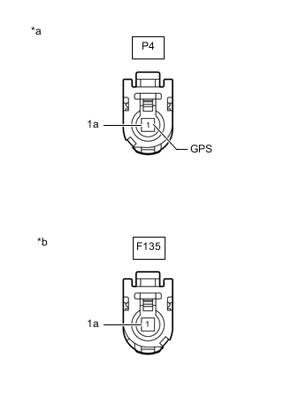
*a Front view of wire harness connector
(to Antenna Divider)
*b Front view of wire harness connector
(to Multi-media Module Receiver Assembly)
Disconnect the P4 antenna divider connector.
-
Disconnect the F135 multi-media module receiver assembly connector.
-
Measure the resistance according to the value(s) in the table below.
Standard Resistance Tester Connection Condition Specified Condition P4-1 (GPS) - F135-1 Always Below 1 Ω P4-1a - F135-1a Always Below 1 Ω P4-1 (GPS) - Body ground Always 10 kΩ or higher P4-1a - Body ground Always 10 kΩ or higher Result Proceed to OK NG
NG
REPAIR OR REPLACE HARNESS OR CONNECTOR
OK
-
-
CHECK TELEPHONE ANTENNA ASSEMBLY
-
Replace the telephone antenna assembly with a new or known good one.
-
Clear the DTCs.
-
Check for DTCs.
OK No DTCs are output. Result Proceed to OK NG
OK
END (TELEPHONE ANTENNA ASSEMBLY IS DEFECTIVE)
NG
-
-
CHECK ANTENNA DIVIDER
-
Replace the antenna divider with a new or known good one.
-
Clear the DTCs.
-
Check for DTCs.
OK No DTCs are output. Result Proceed to OK NG
OK
END (ANTENNA DIVIDER IS DEFECTIVE)
NG
REPLACE MULTI-MEDIA MODULE RECEIVER ASSEMBLY Click here
-