INSTRUMENT PANEL SPEAKER INSTALLATION
CAUTION / NOTICE / HINT
Tech Tips
-
Use the same procedures for the LH side and RH side.
-
The procedures listed below are for the LH side.
-
A bolt without a torque specification is shown in the standard bolt chart Click here.
PROCEDURE
-
INSTALL FRONT NO. 2 SPEAKER ASSEMBLY
-
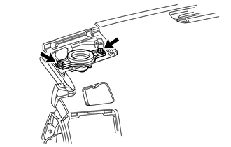
for 9 Speakers Models:
-
Connect the connector.
-
Temporarily install the speaker by aligning the positioning pins of the speaker with the instrument panel.
-
Install the speaker with the 2 bolts.
Note
-
Do not touch the cone part of the speaker.
-
When installing the speaker to the instrument panel be careful that the wires do not get caught between the parts.
-
-
-
except 9 Speakers Models:
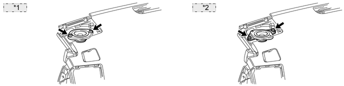
*1 for LHD: *2 for RHD:
-
Connect the connector.
-
Temporarily install the speaker by aligning the positioning pins of the speaker with the instrument panel.
-
Install the speaker with the 2 bolts.
Note
-
Do not touch the cone part of the speaker.
-
When installing the speaker to the instrument panel be careful that the wires do not get caught between the parts.
-
-
-
-
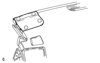
INSTALL NO. 1 INSTRUMENT PANEL SPEAKER PANEL SUB-ASSEMBLY
-
Attach the 4 claws to install the panel.
-
-
INSTALL FRONT PILLAR GARNISH LH
-
INSTALL FRONT ASSIST GRIP SUB-ASSEMBLY
-
INSTALL FRONT NO. 4 SPEAKER ASSEMBLY
-
Connect the speaker connector.
-
Temporarily install the speaker by aligning the positioning pins of the speaker with the instrument panel.
-
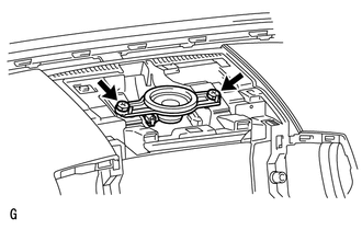
Install the speaker with the 2 bolts.
Note
-
Do not touch the cone part of the speaker.
-
When installing the speaker to the instrument panel be careful that the wires do not get caught between the parts.
-
-
-
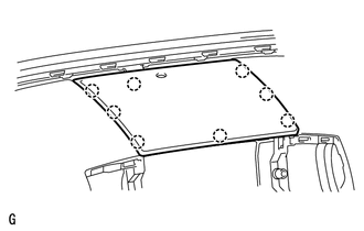
INSTALL NO. 1 SPEAKER OPENING COVER ASSEMBLY
-
Attach the 8 claws to install the opening cover.
-
-
CONNECT CABLE TO NEGATIVE BATTERY TERMINAL
Note
When disconnecting the cable, some systems need to be initialized after the cable is reconnected Click here.