AUDIO AND VISUAL SYSTEM(w/ Multi-display) Display Signal Circuit between Multi-display and Radio Receiver
DESCRIPTION
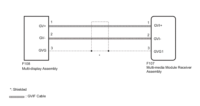
The display image signal from the multi-media module receiver assembly is sent to the multi-display assembly using a digital communication cable.
WIRING DIAGRAM
PROCEDURE
-
CHECK HARNESS AND CONNECTOR (GVIF CABLE)
-
Check if the GVIF cable connectors between the multi-media module receiver assembly and the multi-display assembly have any connection problems.
OK There is no connection problems.
NG 
REMOVE CONNECTION PROBLEM (GVIF CABLE)
OK 
-
-
CHECK HARNESS AND CONNECTOR (GVIF CABLE)
-
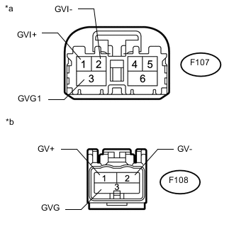
Text in Illustration *a GVIF Cable
(to Multi-media Module Receiver Assembly)
*b GVIF Cable
(to Multi-display Assembly)
Remove the GVIF cable from the multi-media module receiver assembly and multi-display assembly.
-
Measure the resistance according to the value(s) in the table below.
Standard Resistance Tester Connection Condition Specified Condition F107-1 (GVI+) - F108-1 (GV+) Always Below 1 Ω F107-2 (GVI-) - F108-2 (GV-) Always Below 1 Ω F107-3 (GVG1) - F108-3 (GVG) Always Below 1 Ω F107-1 (GVI+) or F108-1 (GV+) - Body ground Always 10 kΩ or higher F107-2 (GVI-) or F108-2 (GV-) - Body ground Always 10 kΩ or higher F107-3 (GVG1) or F108-3 (GVG) - Body ground Always 10 kΩ or higher
NG
REPLACE HARNESS AND CONNECTOR (GVIF CABLE)
OK
-
-
CHECK MULTI-DISPLAY ASSEMBLY
-
Replace the multi-display assembly with a new or known good one Click here.
-
Check that the screen display is normal.
OK Screen display is normal.
OK
END (MULTI-DISPLAY ASSEMBLY IS DEFECTIVE)
NG
PROCEED TO NEXT SUSPECTED AREA SHOWN IN PROBLEM SYMPTOMS TABLE Click here
-