AUDIO AND VISUAL SYSTEM(w/o Navigation System), Diagnostic DTC:74-40
| DTC Code | DTC Name |
|---|---|
| 74-40 | Short in Speaker Circuit |
DESCRIPTION
| DTC No. | DTC Detection Condition | Trouble Area |
|---|---|---|
| 74-40 | Short is detected in the speaker output circuit. |
|
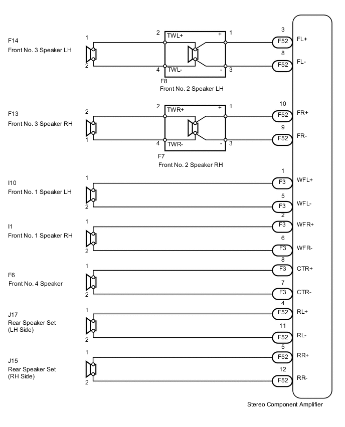
WIRING DIAGRAM
CAUTION / NOTICE / HINT
Tech Tips
After the inspection is completed, clear the DTCs.
PROCEDURE
-
CHECK DTC
-
Disconnect the F3 and F52 amplifier connectors.
-
Clear the DTCs.
-
Check if DTC 74-40 is output.
OK DTC 74-40 is not output.
NG 
REPLACE STEREO COMPONENT AMPLIFIER ASSEMBLY Click here
OK 
-
-
CHECK DTC
-
Reconnect the F52 amplifier connector.
-
Clear the DTCs.
-
Check if DTC 74-40 is output.
OK DTC 74-40 is not output.
NG 
CHECK HARNESS AND CONNECTOR (STEREO COMPONENT AMPLIFIER - SPEAKER) Click here
OK
-
-
CHECK HARNESS AND CONNECTOR (STEREO COMPONENT AMPLIFIER - SPEAKER)
-
Disconnect the F3 amplifier connector.
-
Measure the resistance according to the value(s) in the table below.
Standard Resistance Tester Connection Condition Specified Condition F3-8 (CTR+) - Body ground Always 10 kΩ or higher F3-7 (CTR-) - Body ground Always 10 kΩ or higher F3-1 (WFL+) - Body ground Always 10 kΩ or higher F3-5 (WFL-) - Body ground Always 10 kΩ or higher F3-2 (WFR+) - Body ground Always 10 kΩ or higher F3-6 (WFR-) - Body ground Always 10 kΩ or higher
NG
REPAIR OR REPLACE HARNESS OR CONNECTOR
OK
-
-
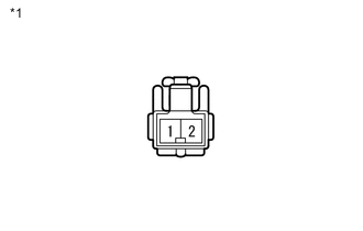
INSPECT FRONT NO. 1 SPEAKER ASSEMBLY
-
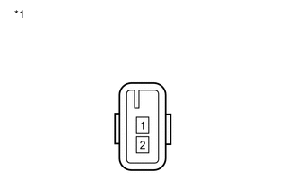
Text in Illustration *1 Component without harness connected
(Front No. 1 Speaker)
Disconnect the I10 and I1 speaker connectors.
-
Measure the resistance according to the value(s) in the table below.
Standard Resistance Tester Connection Condition Specified Condition 1 - 2 Always 3 Ω
NG
REPLACE FRONT NO. 1 SPEAKER ASSEMBLY Click here
OK
-
-
INSPECT FRONT NO. 4 SPEAKER ASSEMBLY
-
Text in Illustration *1 Component without harness connected
(Front No. 4 Speaker)
Disconnect the F6 speaker connector.
-
Measure the resistance according to the value(s) in the table below.
Standard Resistance Tester Connection Condition Specified Condition 1 - 2 Always 6 Ω
OK
REPLACE STEREO COMPONENT AMPLIFIER ASSEMBLY Click here
NG
REPLACE FRONT NO. 4 SPEAKER ASSEMBLY Click here
-
-
CHECK HARNESS AND CONNECTOR (STEREO COMPONENT AMPLIFIER - SPEAKER)
-
Disconnect the F52 amplifier connector.
-
Measure the resistance according to the value(s) in the table below.
Standard Resistance Tester Connection Condition Specified Condition F52-8 (FL-) - Body ground Always 10 kΩ or higher F52-3 (FL+) - Body ground Always 10 kΩ or higher F52-9 (FR-) - Body ground Always 10 kΩ or higher F52-10 (FR+) - Body ground Always 10 kΩ or higher F52-5 (RR+) - Body ground Always 10 kΩ or higher F52-12 (RR-) - Body ground Always 10 kΩ or higher F52-4 (RL+) - Body ground Always 10 kΩ or higher F52-11 (RL-) - Body ground Always 10 kΩ or higher
NG
REPAIR OR REPLACE HARNESS OR CONNECTOR
OK
-
-
INSPECT REAR SPEAKER SET
-
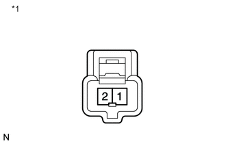
Text in Illustration *1 Component without harness connected
(Rear Speaker Set)
Disconnect the J17 and J15 speaker connectors.
-
Measure the resistance according to the value(s) in the table below.
Standard Resistance Tester Connection Condition Specified Condition 1 - 2 Always 4 Ω
NG
REPLACE REAR SPEAKER SET Click here
OK
-
-
INSPECT FRONT NO. 2 SPEAKER ASSEMBLY
-
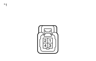
Text in Illustration *1 Component without harness connected
(Front No. 2 Speaker)
Disconnect the F8 and F7 speaker connectors.
-
Measure the resistance according to the value(s) in the table below.
Standard Resistance Tester Connection Condition Specified Condition 1 - 2 Always Below 1 Ω 3 - 4 Always Below 1 Ω 2 - 4 Always 4 Ω
NG
REPLACE FRONT NO. 2 SPEAKER ASSEMBLY Click here
OK
-
-
INSPECT FRONT NO. 3 SPEAKER ASSEMBLY
-
Text in Illustration *1 Component without harness connected
(Front No. 3 Speaker)
Disconnect the F14 and F13 speaker connectors.
-
Measure the resistance according to the value(s) in the table below.
Standard Resistance Tester Connection Condition Specified Condition 1 - 2 Always 4 Ω
NG
REPLACE FRONT NO. 3 SPEAKER ASSEMBLY Click here
OK
-
-
CHECK HARNESS AND CONNECTOR (FRONT NO. 2 SPEAKER - FRONT NO. 3 SPEAKER)
-
Disconnect the F8, F7, F14 and F13 speaker connectors.
-
Measure the resistance according to the value(s) in the table below.
Standard Resistance for LH Tester Connection Condition Specified Condition F8-2 (TWL+) - F14-1 Always Below 1 Ω F8-4 (TWL-) - F14-2 F8-2 (TWL+) - Body ground Always 10 kΩ or higher F8-4 (TWL-) - Body ground for RH Tester Connection Condition Specified Condition F7-2 (TWR+) - F13-1 Always Below 1 Ω F7-4 (TWR-) - F13-2 F7-2 (TWR+) - Body ground Always 10 kΩ or higher F7-4 (TWR-) - Body ground
OK
REPLACE STEREO COMPONENT AMPLIFIER ASSEMBLY Click here
NG
REPAIR OR REPLACE HARNESS OR CONNECTOR
-