STEERING COLUMN ASSEMBLY(for Power Tilt and Power Telescopic Steering Column) INSTALLATION
CAUTION / NOTICE / HINT
Tech Tips
-
Use the same procedure for RHD and LHD vehicles.
-
The procedure listed below is for LHD vehicles.
PROCEDURE
-
CONNECT NO. 2 STEERING INTERMEDIATE SHAFT
-
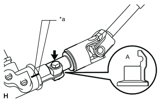
Text in Illustration *a Matchmark Align the part of the dust cover labeled A with the No. 2 steering intermediate shaft, and install the No. 2 steering intermediate shaft assembly to the steering link assembly.
-
Install the bolt.
- Torque:
- 35 N*m { 357 kgf*cm, 26 ft.*lbf }
Note
Be careful not to damage the dust cover.
-
-
INSTALL STEERING COLUMN HOLE COVER SUB-ASSEMBLY
-
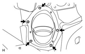
Install the 4 bolts and nut.
- Torque:
- 5.0 N*m { 51 kgf*cm, 44 in.*lbf }
Note
Do not fold back the boot part of the steering hole cover or extend it excessively. if it is extended excessively, return it to its original position.
Tech Tips
Install the steering intermediate shaft assembly from the inside of the vehicle.
-
Install the clamp to the steering column hole cover.
-
-
CONNECT STEERING ACTUATOR ASSEMBLY
-
INSTALL STEERING COLUMN ASSEMBLY (TILT STEERING GEAR ASSEMBLY WITH MOTOR)
-
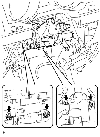
Install the 4 nuts and steering column.
- Torque:
- 26 N*m { 265 kgf*cm, 19 ft.*lbf }
-
-
INSTALL NO. 3 AIR DUCT SUB-ASSEMBLY
-
INSTALL WIRE HARNESS PROTECTOR AND WIRE HARNESS
-
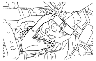
Attach the 3 claws and install the wiring harness protector and wire harness.
-
-
INSTALL DRIVER SIDE KNEE AIRBAG ASSEMBLY (w/ Driver Side Knee Airbag)
-
INSTALL LOWER INSTRUMENT PANEL SUB-ASSEMBLY (w/o Driver Side Knee Airbag)
-
INSTALL NO. 1 SWITCH HOLE BASE
-
INSTALL LOWER NO. 1 INSTRUMENT PANEL FINISH PANEL
-
INSTALL COWL SIDE TRIM BOARD LH
-
INSTALL NO. 1 INSTRUMENT PANEL UNDER COVER SUB-ASSEMBLY (w/ Floor Under Cover)
-
INSTALL FRONT DOOR SCUFF PLATE LH
-
INSTALL INSTRUMENT CLUSTER FINISH PANEL SUB-ASSEMBLY (w/ Multi-information Display)
-
INSTALL INSTRUMENT CLUSTER FINISH PANEL SUB-ASSEMBLY (w/o Multi-information Display)
-
INSTALL NO. 2 INSTRUMENT CLUSTER FINISH PANEL GARNISH
-
INSTALL NO. 1 INSTRUMENT CLUSTER FINISH PANEL GARNISH
-
INSTALL INSTRUMENT SIDE PANEL LH
-
INSTALL LOWER INSTRUMENT PANEL PAD SUB-ASSEMBLY LH
-
INSTALL NO. 2 INSTRUMENT PANEL FINISH PANEL CUSHION
-
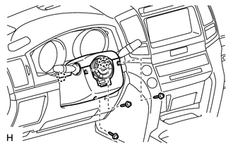
INSTALL COMBINATION SWITCH ASSEMBLY WITH SPIRAL CABLE SUB-ASSEMBLY
-
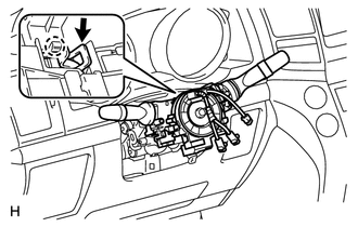
Using pliers, grip the claws of the clamp and install the turn signal switch assembly with spiral cable sub-assembly to the steering column assembly with the clamp.
-
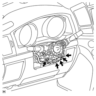
Connect the 5 connectors to the turn signal switch with spiral cable.
-
-
INSTALL TILT AND TELESCOPIC SWITCH
-
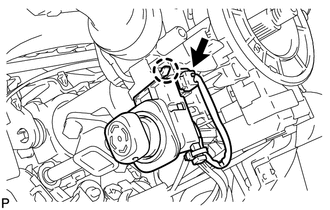
Attach the claw to install the switch.
-
Connect the switch connector.
-
-
INSTALL UPPER STEERING COLUMN COVER
-
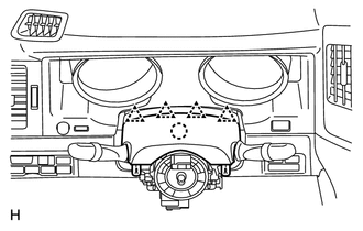
Attach the claw to install the upper steering column cover.
-
Attach the 4 clips to install the upper steering column cover onto the instrument cluster finish panel.
-
-
INSTALL LOWER STEERING COLUMN COVER
-
Attach the 2 claws to install the lower steering column cover.
Note
Do not damage the tilt and telescopic switch.
-
Install the 3 screws.
- Torque:
- 1.5 N*m { 15 kgf*cm, 13 in.*lbf }
-
-
INSTALL STEERING WHEEL ASSEMBLY
-
INSTALL STEERING PAD
-
INSTALL LOWER NO. 2 STEERING WHEEL COVER
-
INSTALL LOWER NO. 3 STEERING WHEEL COVER
-
CHECK FRONT WHEELS FACING STRAIGHT AHEAD
-
INSTALL FRONT WHEELS
-
CONNECT CABLE TO NEGATIVE BATTERY TERMINAL
Note
-
Reset the AUTO TILT AWAY function setting to the previous condition by changing the customize parameter Click here.
-
When disconnecting the cable, some systems need to be initialized after the cable is reconnected Click here.
-
-
INSPECT SRS WARNING LIGHT
-
Inspect the SRS warning light Click here.
-