STEERING COLUMN ASSEMBLY(for Power Tilt and Power Telescopic Steering Column) ON-VEHICLE INSPECTION
PROCEDURE
-
DISCONNECT CABLE FROM NEGATIVE BATTERY TERMINAL
CAUTION:
Wait at least 90 seconds after disconnecting the cable from the negative (-) battery terminal to disable the SRS system.
Note
When disconnecting the cable, some systems need to be initialized after the cable is reconnected Click here.
-
REMOVE LOWER STEERING COLUMN COVER
-
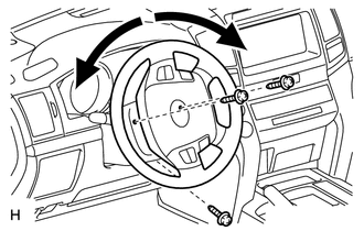
Remove the 3 screws.
Tech Tips
Turn the steering wheel to the right and left as necessary to remove the 2 screws.
-
Detach the 2 claws to remove the lower steering column cover.
-
-
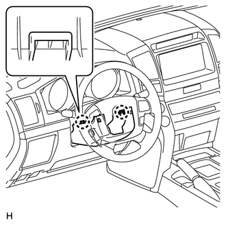
REMOVE UPPER STEERING COLUMN COVER
-
Detach the 4 clips.
-
Detach the claw to remove the upper steering column cover.
-
-
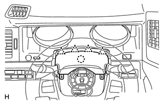
REMOVE DRIVER SIDE KNEE AIRBAG ASSEMBLY
-
Remove the driver side knee airbag assembly Click here.
-
-
INSPECT TILT MOTOR
-
Inspect the tilt motor.
-
Disconnect connector A from the multiplex tilt and telescopic ECU.
-
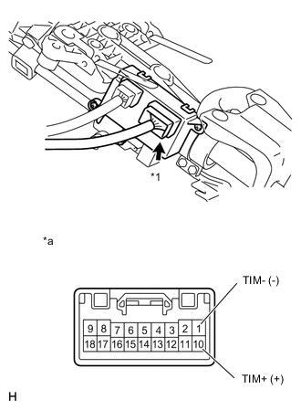
Text in Illustration *1 Connector A *a Front view of wire harness connector
(to Multiplex Tilt and Telescopic ECU)
Apply battery voltage to the tilt motor connector, and check the steering wheel tilt operation.
OK Measurement Condition Specified Condition Battery positive (+) → Terminal 10 (TIM+)
Battery negative (-) → Terminal 1(TIM-)
Steering wheel tilts up -
Text in Illustration *1 Connector A *a Front view of wire harness connector
(to Multiplex Tilt and Telescopic ECU)
Apply battery voltage to the tilt motor connector, and check the steering wheel tilt operation.
OK Measurement Condition Specified Condition Battery positive (+) → Terminal 1 (TIM-)
Battery negative (-) → Terminal 10 (TIM+)
Steering wheel tilts down If the steering wheel does not tilt down, replace the steering column assembly.
-
-
-
INSPECT TELESCOPIC MOTOR
-
Inspect the telescopic motor.
-
Disconnect connector B from the multiplex tilt and telescopic ECU.
-
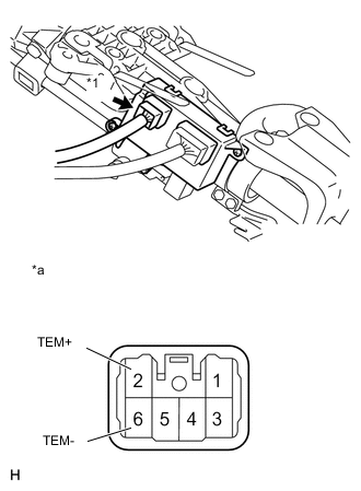
Text in Illustration *1 Connector B *a Front view of wire harness connector
(to Multiplex Tilt and Telescopic ECU)
Apply battery voltage to the telescopic motor connector, and check the steering column operation.
OK Measurement Condition Specified Condition Battery positive (+) → Terminal 2 (TEM+)
Battery negative (-) → Terminal 6 (TEM-)
Steering column contracts -
Text in Illustration *1 Connector B *a Front view of wire harness connector
(to Multiplex Tilt and Telescopic ECU)
Apply battery voltage to the telescopic motor connector, and check the steering column operation.
OK Measurement Condition Specified Condition Battery positive (+) → Terminal 6 (TEM-)
Battery negative (-) → Terminal 2 (TEM+)
Steering column extends If the steering column operation does not match the specified condition, replace the steering column.
-
-
-
INSTALL DRIVER SIDE KNEE AIRBAG ASSEMBLY
-
Install driver side knee airbag assembly Click here.
-
-
INSTALL LOWER STEERING COLUMN COVER
-
Attach the 2 claws to install the lower steering column cover.
-
-
INSTALL UPPER STEERING COLUMN COVER
-
Attach the claw to install the upper steering column cover.
-
Attach the 4 clips to install the upper steering cover onto the instrument panel cluster finish panel.
-
Install the 3 screws.
- Torque:
- 2.0 N*m { 20 kgf*cm, 18 in.*lbf }
Tech Tips
Turn the steering wheel to the right and left as necessary to install the 2 screws.
-
-
INSPECT SRS WARNING LIGHT
-
Inspect the SRS warning light Click here.
-
-
CONNECT CABLE TO NEGATIVE BATTERY TERMINAL
Note
When disconnecting the cable, some systems need to be initialized after the cable is reconnected Click here.