STEERING COLUMN ASSEMBLY(for Manual Tilt and Manual Telescopic Steering Column) INSTALLATION

CAUTION / NOTICE / HINT
Tech Tips
-
Use the same procedure for RHD and LHD vehicles.
-
The procedure listed below is for LHD vehicles.
PROCEDURE
-
CONNECT NO. 2 STEERING INTERMEDIATE SHAFT
-
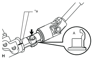
Text in Illustration *a Matchmark Align the part of the dust cover labeled A with the No. 2 steering intermediate shaft, and install the No. 2 steering intermediate shaft assembly to the steering link assembly.
-
Install the bolt.
- Torque:
- 35 N*m { 357 kgf*cm, 26 ft.*lbf }
Note
Be careful not to damage the dust cover.
-
-
INSTALL STEERING COLUMN HOLE COVER SUB-ASSEMBLY
-
Install the 4 bolts and nut.
- Torque:
- 5.0 N*m { 51 kgf*cm, 44 in.*lbf }
Note
Do not fold back the boot part of the steering hole cover or extend it excessively. if it is extended excessively, return it to its original position.
Tech Tips
Install the steering intermediate shaft assembly from the inside of the vehicle.
-
Using needle nose pliers, lock the clamp to the steering column hole cover to install it.
Note
Be careful when performing the operation as the clamp may not lock if the claws of the clamp are deformed.
-
-
CONNECT STEERING INTERMEDIATE SHAFT ASSEMBLY
-
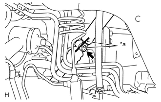
Text in Illustration *a Matchmark Align the matchmarks on the No. 2 steering intermediate shaft assembly and the steering intermediate shaft assembly.
Tech Tips
Install the steering intermediate shaft from the inside of the vehicle.
-
Install the bolt.
- Torque:
- 35 N*m { 357 kgf*cm, 26 ft.*lbf }
-
-
INSTALL STEERING COLUMN ASSEMBLY
-
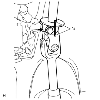
Text in Illustration *a Matchmark Align the matchmarks on the steering intermediate shaft and the steering column.
-
Install the bolt.
- Torque:
- 35 N*m { 357 kgf*cm, 26 ft.*lbf }
-
w/o Entry and Start System:
-
Install the steering column with the 4 nuts.
- Torque:
- 21 N*m { 214 kgf*cm, 15 ft.*lbf }
-
-
w/ Entry and Start System
-
Install the steering column with the 4 nuts.
- Torque:
- 26 N*m { 265 kgf*cm, 19 ft.*lbf }
-
-
-
INSTALL NO. 3 AIR DUCT SUB-ASSEMBLY
-
INSTALL WIRE HARNESS PROTECTOR AND WIRE HARNESS
-
Attach the 2 claws to connect the wire harness protector and wire harness.
-
Connect the 2 wire harness clamps.
-
-
INSTALL LOWER NO. 1 INSTRUMENT PANEL AIRBAG ASSEMBLY (w/ Driver Side Knee Airbag)
-
INSTALL LOWER INSTRUMENT PANEL SUB-ASSEMBLY (w/o Driver Side Knee Airbag)
-
INSTALL COMBINATION SWITCH ASSEMBLY WITH SPIRAL CABLE SUB-ASSEMBLY
-
Using pliers, grip the claws of the clamp and install the combination switch assembly with spiral cable sub-assembly to the steering column assembly with the clamp.
-
Connect the connectors to the combination switch with spiral cable.
-
-
INSTALL UPPER STEERING COLUMN COVER
-
Attach the claw to install the upper steering column cover.
-
Attach the 4 clips and 2 claws to install the upper steering column cover onto the meter hood spacer.
-
-
INSTALL LOWER STEERING COLUMN COVER
-
Attach the 2 claws to install the lower steering column cover.
-
Install the 3 screws.
- Torque:
- 1.5 N*m { 15 kgf*cm, 13 in.*lbf }
-
-
INSTALL STEERING WHEEL ASSEMBLY
-
CHECK FRONT WHEELS FACING STRAIGHT AHEAD
-
INSTALL FRONT WHEEL
-
CONNECT CABLE TO NEGATIVE BATTERY TERMINAL
Note
When disconnecting the cable, some systems need to be initialized after the cable is reconnected Click here.
-
INSPECT SRS WARNING LIGHT