CAUTION / NOTICE / HINT
-
Use the same procedure for RHD and LHD vehicles.
-
The procedure listed below is for LHD vehicles.
PROCEDURE
- Click here
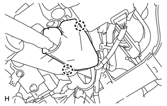
CONNECT NO. 2 STEERING INTERMEDIATE SHAFT
-
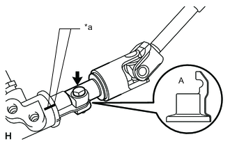
Align the part of the dust cover labeled A with the No. 2 steering intermediate shaft, and install the No. 2 steering intermediate shaft assembly to the steering link assembly.
Table 1. Text in Illustration *a Matchmark -
Install the bolt.
35 N*m 357 kgf*cm 26 ft.*lbf Note:Be careful not to damage the dust cover.
-
- Click here
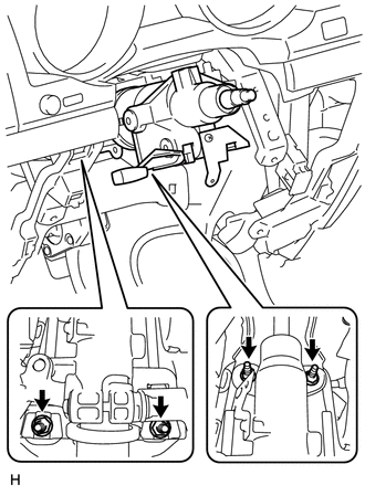
INSTALL STEERING COLUMN HOLE COVER SUB-ASSEMBLY
-
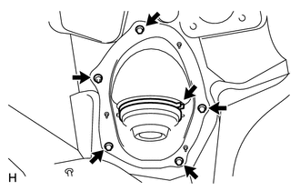
Install the 4 bolts and nut.
5.0 N*m 51 kgf*cm 44 in.*lbf Note:Do not fold back the boot part of the steering hole cover or extend it excessively. if it is extended excessively, return it to its original position.
Tip:Install the steering intermediate shaft assembly from the inside of the vehicle.
-
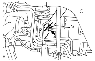
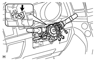
Using needle nose pliers, lock the clamp to the steering column hole cover to install it.
Note:Be careful when performing the operation as the clamp may not lock if the claws of the clamp are deformed.
-
- Click here
CONNECT STEERING INTERMEDIATE SHAFT ASSEMBLY
-
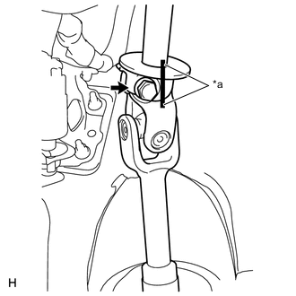
Align the matchmarks on the No. 2 steering intermediate shaft assembly and the steering intermediate shaft assembly.
Table 2. Text in Illustration *a Matchmark Tip:Install the steering intermediate shaft from the inside of the vehicle.
-
Install the bolt.
35 N*m 357 kgf*cm 26 ft.*lbf
-
- Click here
INSTALL STEERING COLUMN ASSEMBLY
-
Align the matchmarks on the steering intermediate shaft and the steering column.
-
Install the bolt.
Table 3. Text in Illustration *a Matchmark 35 N*m 357 kgf*cm 26 ft.*lbf -
w/o Entry and Start System:
-
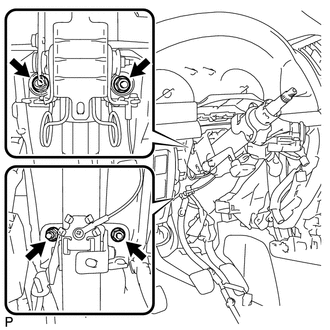
Install the steering column with the 4 nuts.
21 N*m 214 kgf*cm 15 ft.*lbf
-
-
w/ Entry and Start System
-
Install the steering column with the 4 nuts.
26 N*m 265 kgf*cm 19 ft.*lbf
-
-
- Click here
INSTALL NO. 3 AIR DUCT SUB-ASSEMBLY
- Click here
INSTALL WIRE HARNESS PROTECTOR AND WIRE HARNESS
-
Attach the 2 claws to connect the wire harness protector and wire harness.
-
- Click here
INSTALL DRIVER SIDE KNEE AIRBAG ASSEMBLY (w/ Driver Side Knee Airbag)
- Click here
INSTALL LOWER INSTRUMENT PANEL SUB-ASSEMBLY (w/o Driver Side Knee Airbag)
- Click here
INSTALL NO. 1 SWITCH HOLE BASE
- Click here
INSTALL LOWER NO. 1 INSTRUMENT PANEL FINISH PANEL
- Click here
INSTALL COWL SIDE TRIM BOARD LH
- Click here
INSTALL NO. 1 INSTRUMENT PANEL UNDER COVER SUB-ASSEMBLY (w/ Floor Under Cover)
- Click here
INSTALL FRONT DOOR SCUFF PLATE LH
- Click here
INSTALL INSTRUMENT CLUSTER FINISH PANEL SUB-ASSEMBLY (w/o Multi-information Display)
- Click here
INSTALL INSTRUMENT CLUSTER FINISH PANEL SUB-ASSEMBLY (w/ Multi-information Display)
- Click here
INSTALL NO. 2 INSTRUMENT CLUSTER FINISH PANEL GARNISH
- Click here
INSTALL NO. 1 INSTRUMENT CLUSTER FINISH PANEL GARNISH
- Click here
INSTALL INSTRUMENT SIDE PANEL LH
- Click here
INSTALL LOWER INSTRUMENT PANEL PAD SUB-ASSEMBLY LH
- Click here
INSTALL NO. 2 INSTRUMENT PANEL FINISH PANEL CUSHION
- Click here
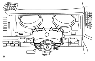
INSTALL COMBINATION SWITCH ASSEMBLY WITH SPIRAL CABLE SUB-ASSEMBLY
-
Using pliers, grip the claws of the clamp and install the combination switch assembly with spiral cable sub-assembly to the steering column assembly with the clamp.
-
Connect the connectors to the combination switch with spiral cable.
-
- Click here
INSTALL UPPER STEERING COLUMN COVER
-
Attach the claw to install the upper steering column cover.
-
Attach the 4 clips to install the upper steering column cover onto the instrument cluster finish panel.
-
- Click here
INSTALL LOWER STEERING COLUMN COVER
-
Attach the 2 claws to install the lower steering column cover.
-
Install the 3 screws.
-
- Click here
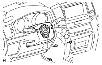
INSTALL STEERING WHEEL ASSEMBLY
- Click here
INSTALL STEERING PAD
- Click here
INSTALL LOWER NO. 2 STEERING WHEEL COVER
- Click here
INSTALL LOWER NO. 3 STEERING WHEEL COVER
- Click here
CHECK FRONT WHEELS FACING STRAIGHT AHEAD
- Click here
INSTALL FRONT WHEEL
- Click here
CONNECT CABLE TO NEGATIVE BATTERY TERMINAL
Note:When disconnecting the cable, some systems need to be initialized after the cable is reconnected (Click here).
- Click here
INSPECT SRS WARNING LIGHT
-
Inspect the SRS warning light (Click here).
-