STEERING COLUMN ASSEMBLY(for Manual Tilt and Manual Telescopic Steering Column) REASSEMBLY

CAUTION / NOTICE / HINT
Note
When using a vise, do not overtighten it.
PROCEDURE
-
INSTALL STEERING MAIN SHAFT ASSEMBLY (w/o Entry and Start System)
-
Install the steering main shaft assembly to the steering column upper tube.
-
*1 Snap Ring Expander *2 Snap Ring Using a snap ring expander, install a new shaft snap ring to the steering main shaft assembly.
Note
-
Make sure the steering main shaft snap ring is securely installed to the groove.
-
Do not damage the steering main shaft assembly.
-
-
-
INSTALL NO. 1 TILT STEERING SUPPORT COLLAR (w/o Entry and Start System)
-
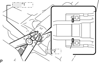
Install the 2 No. 1 tilt steering support collars to the steering lower column tube assembly.
Note
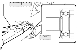
When installing the No. 1 tilt steering support collar, make sure that the cutout portion is aligned as shown in the illustration.
-
-
INSTALL STEERING COLUMN BRACKET SPACER (w/o Entry and Start System)
-
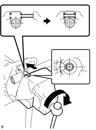
Clamp the steering column bracket spacer and steering lower column tube assembly in a vise between a cloth and aluminum plates, and install the steering column bracket spacer to the steering lower column tube assembly using the vise.
Note
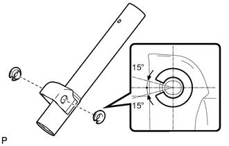
When installing the steering column bracket spacer, make sure that it is positioned so that the inner diameter is as shown in the illustration.
-
-
INSTALL TELESCOPIC STEERING GUIDE (w/o Entry and Start System)
-
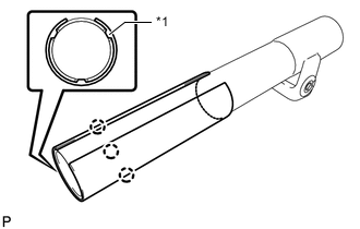
*1 Match Align the 3 protrusions of the telescopic steering guide with the 3 holes of the steering lower column tube assembly and install the telescopic steering guide.
-
-
INSTALL STEERING LOWER COLUMN TUBE ASSEMBLY (w/o Entry and Start System)
-
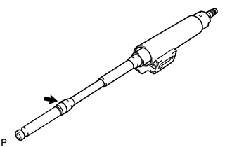
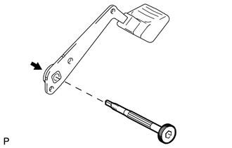
Apply MP grease to the area of the steering main shaft assembly indicated by the arrow in the illustration.
-
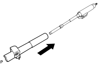
Install the steering lower column tube assembly to the steering column upper tube.
-
-
INSTALL TILT STEERING SUPPORT (w/o Entry and Start System)
-
Install the tilt steering support with the bolt.
- Torque:
- 15 N*m { 153 kgf*cm, 11 ft.*lbf }
-
-
INSTALL NO. 1 STEERING COLUMN RING (w/o Entry and Start System)
-
*1 Snap Ring Expander *2 Snap Ring Using a snap ring expander, install a new No. 1 steering column ring to the steering main shaft.
Note
-
Make sure the No. 1 steering column ring is securely installed to the groove.
-
Do not damage the steering main shaft assembly.
-
-
-
INSTALL TILT STEERING PAWL ASSEMBLY (w/o Entry and Start System)
-
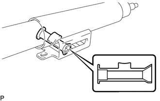
Install the tilt steering pawl assembly to the steering column upper tube.
Note
When installing the tilt steering pawl assembly, position the opening as shown in the illustration.
-
-
INSTALL BREAK AWAY BRACKET (w/o Entry and Start System)
-
Apply MP grease to the sliding areas of a new break away bracket and install it to the steering column upper tube.
-
-
INSTALL STEERING COLUMN TUBE STOPPER (w/o Entry and Start System)
-
*1 Parallel Apply MP grease to the sliding surface of the steering column tube stopper (the one with the groove) and install it to the break away bracket.
Note
Align the flat edge of the steering column tube stopper and the raised sliding area of the break away bracket as shown in the illustration.
-
*1 Parallel Apply MP grease to the sliding surface of the steering column tube stopper (the one without the groove) and install it to the break away bracket.
Note
Align the flat edge of the steering column tube stopper and the raised sliding area of the break away bracket as shown in the illustration.
-
-
INSTALL NO. 1 TILT LEVER LOCK BOLT (w/o Entry and Start System)
-
Apply MP grease to the sliding surface of the steering tilt lever and install it to the No. 1 tilt lever lock bolt.
-
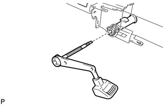
Install the No. 1 tilt lever lock bolt to the break away bracket.
Note
-
Do not drop the steering column tube stopper.
-
Pass the No. 1 tilt lever lock bolt through the hole of the tilt steering pawl assembly.
-
-
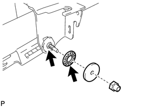
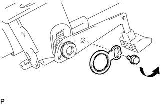
Apply MP grease to the sliding surface of the thrust needle roller bearing and install it to the No. 1 tilt lever lock bolt.
-
Temporarily install the tilt steering rotor to the No. 1 tilt lever lock bolt with a new No. 1 tilt steering adjusting nut.
-
Using an 8 mm socket hexagon wrench, tighten the No. 1 tilt lever lock bolt.
- Torque:
- 2.0 N*m { 20 kgf*cm, 18 in.*lbf }
Note
The tightening direction for the No. 1 tilt lever lock bolt is the tightening direction for bolts with a left-handed thread.
-
-
INSTALL NO. 1 TILT STEERING SUPPORT REINFORCEMENT (w/o Entry and Start System)
-
Install the No. 1 tilt steering support reinforcement to the steering tilt lever with the steering tilt lever bolt.
- Torque:
- 5.4 N*m { 55 kgf*cm, 48 in.*lbf }
Note
The tightening direction for the steering tilt lever bolt is the tightening direction for bolts with a left-handed thread.
-
-
TIGHTEN NO. 1 TILT STEERING ADJUSTING NUT (w/o Entry and Start System)
-
Lock the steering tilt lever.
-
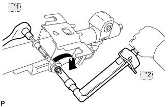
*1 Hold *2 Turn Using an 8 mm socket hexagon wrench, hold the No. 1 tilt lever lock bolt in place and tighten the No. 1 tilt steering adjusting nut.
- Torque:
- 3.0 N*m { 31 kgf*cm, 27 in.*lbf }
-
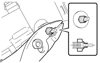
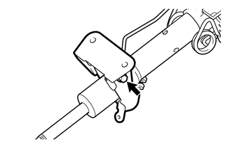
Using pliers, stake the No. 1 tilt steering adjusting nut as shown in the illustration.
Note
After staking the No. 1 tilt steering adjusting nut, make sure it is not loose.
-
-
INSTALL TILT STEERING JUMP UP SPRING (w/o Entry and Start System)
-
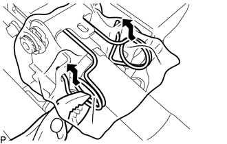
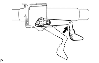
Using pliers, move the tilt steering jump up spring in the direction indicated by the arrow in the illustration to install it to the break away bracket.
Note
To avoid spatter, cover the area with a cloth.
-
-
INSTALL TILT LEVER RETURN SPRING (w/o Entry and Start System)
-
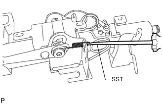
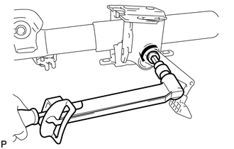
Using SST, install the tilt lever return spring to the break away bracket and steering tilt lever.
- SST
- 09921-00010
Note
-
To avoid spatter, cover the area with a cloth.
-
Do not let the damper fall off of the tilt lever return spring.
-
-
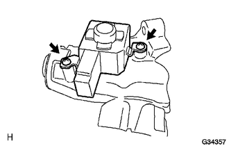
INSTALL TILT STEERING SUPPORT BOND CABLE (w/o Entry and Start System)
-
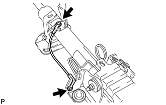
Install the steering support bond cable to the steering column with the 2 screws.
-
-
INSTALL BREAK AWAY COLLAR SUB-ASSEMBLY (w/o Entry and Start System)
-
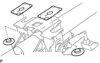
*1 Break Away Collar Install the 2 new break away collars and 2 new break away capsules to the break away bracket.
Note
Do not compress the disc spring portion of the break away collar.
-
-
INSTALL IGNITION OR STARTER SWITCH ASSEMBLY (w/o Entry and Start System)
-
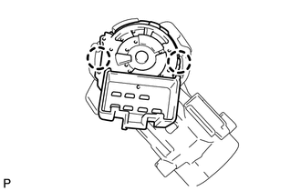
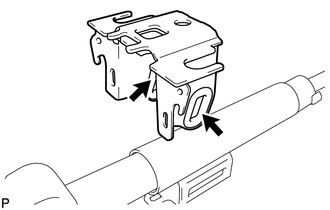
Attach the 2 claws to install the ignition or starter switch assembly to the steering column upper bracket assembly.
-
-
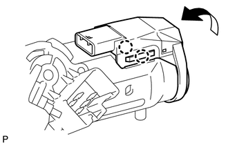
INSTALL UNLOCK WARNING SWITCH ASSEMBLY (w/o Entry and Start System)
-
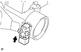
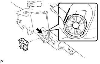
Attach the 2 claws to install the unlock warning switch assembly to the steering column upper bracket assembly.
Tech Tips
Move the unlock warning switch assembly in the direction indicated by the arrow in the illustration to install it.
-
-
INSTALL IGNITION SWITCH LOCK CYLINDER ASSEMBLY (w/o Entry and Start System)
-
Turn the ignition switch lock cylinder assembly to ACC.
-
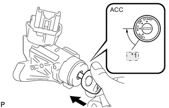
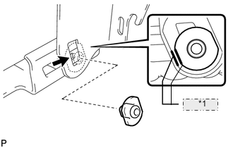
*1 LOCK Insert the ignition switch lock cylinder assembly into the steering column upper bracket assembly to install it.
-
Check that the ignition switch lock cylinder assembly is securely fixed in place.
-
-
INSPECT STEERING LOCK OPERATION (w/o Entry and Start System)
-
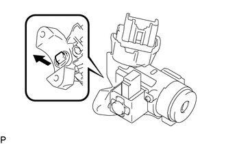
Remove the key and check that the steering lock operates.
-
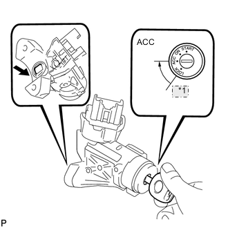
*1 LOCK Insert the key, turn the ignition switch to ACC and check that the steering lock disengages.
-
-
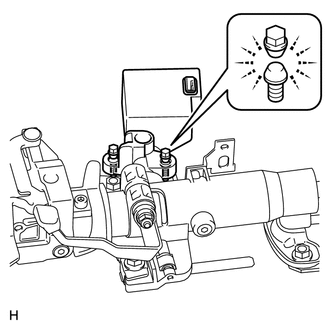
INSTALL STEERING COLUMN UPPER WITH SWITCH BRACKET ASSEMBLY (w/o Entry and Start System)
-
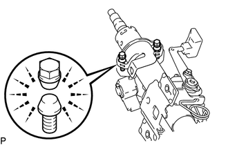
Install the steering column upper with switch bracket assembly and steering column upper clamp with 2 new steering lock set bolts, and tighten the bolts until the heads break off.
-
-
INSTALL TRANSPONDER KEY AMPLIFIER (w/o Entry and Start System)
-
Attach the 2 claws to install the transponder key amplifier to the steering column upper with switch bracket assembly.
-
-
INSTALL KEY INTERLOCK SOLENOID (for Automatic Transmission)
-
Install the key interlock solenoid to the steering column upper bracket with the 2 screws.
-
-
INSTALL STEERING LOCK ACTUATOR ASSEMBLY (w/ Entry and Start System)
-
Temporarily install the steering lock actuator assembly with 2 new tapered-head bolts.
-
Tighten the 2 tapered-head bolts until the bolt heads break off.
-