STEERING LINKAGE REMOVAL

CAUTION / NOTICE / HINT
CAUTION:
Some of these service operations affect the SRS airbag system. Read the precautionary notices concerning the SRS airbag system before servicing the steering column Click here.
Tech Tips
-
Use the same procedure for RHD and LHD vehicles.
-
The procedure listed below is for LHD vehicles.
PROCEDURE
-
PLACE FRONT WHEELS FACING STRAIGHT AHEAD
-
REMOVE ENGINE ASSEMBLY
-
for 1UR-FE:
Remove the engine Click here.
-
for 1GR-FE:
Remove the engine Click here.
-
for 1VD-FTV:
Remove the engine Click here.
-
for 3UR-FE:
Remove the engine Click here.
-
-
REMOVE FRONT WHEELS
-
LOOSEN NO. 1 FRONT STABILIZER BRACKET LH
-
w/ KDSS:
Loosen the bracket Click here.
-
w/o KDSS:
Loosen the bracket Click here.
-
-
LOOSEN NO. 1 FRONT STABILIZER BRACKET RH
Tech Tips
Use the same procedures described for the LH side.
-
REMOVE FRONT STABILIZER LINK ASSEMBLY LH
-
w/ KDSS:
Remove the front stabilizer link Click here.
-
w/o KDSS:
Remove the front stabilizer link Click here.
-
-
REMOVE FRONT STABILIZER LINK ASSEMBLY RH
Tech Tips
Use the same procedures described for the LH side.
-
REMOVE FRONT NO. 1 STABILIZER BRACKET LH
-
w/ KDSS:
Remove the stabilizer bracket Click here.
-
w/o KDSS:
Remove the front bracket Click here.
-
-
REMOVE FRONT NO. 1 STABILIZER BRACKET RH
Tech Tips
Use the same procedures described for the LH side.
-
REMOVE FRONT STABILIZER BAR
-
w/ KDSS:
Remove the stabilizer bar Click here.
-
w/o KDSS:
Remove the stabilizer bar Click here.
-
-
DISCONNECT NO. 2 STEERING INTERMEDIATE SHAFT
-
for Manual Tilt and Telescopic:
Disconnect the No. 2 steering intermediate shaft Click here.
-
for Power Tilt and Power Telescopic:
Disconnect the No. 2 steering intermediate shaft Click here.
-
-
DISCONNECT TIE ROD END SUB-ASSEMBLY LH
-
DISCONNECT TIE ROD END SUB-ASSEMBLY RH
Tech Tips
Use the same procedures described for the LH side.
-
REMOVE TIE ROD END SUB-ASSEMBLY LH
-
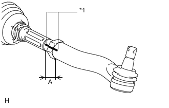
*1 Matchmark Put matchmarks on the tie rod end LH and steering rack end.
-
Measure length A and record the measurement.
-
Remove the tie rod end LH.
-
-
REMOVE TIE ROD END SUB-ASSEMBLY RH
Tech Tips
Use the same procedures described for the LH side.
-
REMOVE STEERING RACK BOOT PROTECTOR LH
-
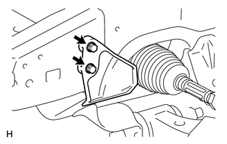
Remove the 2 bolts and steering rack boot protector.
-
-
REMOVE STEERING RACK BOOT PROTECTOR RH
Tech Tips
Use the same procedures described for the LH side.
-
DISCONNECT PRESSURE FEED TUBE ASSEMBLY
-
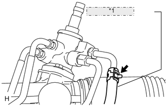
*1 Return Tube Side Remove the clamp and disconnect the pressure feed tube (return tube side) from the power steering link.
-
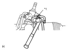
*1 Union Nut Wrench Using a union nut wrench, disconnect the pressure feed tube (pressure feed tube side) from the power steering link.
-
Remove the 2 bolts and disconnect the pressure feed tube clamp.
-
-
REMOVE FRONT SUSPENSION REBOUND STOPPER SUB-ASSEMBLY LH
-
REMOVE FRONT SUSPENSION REBOUND STOPPER SUB-ASSEMBLY RH
-
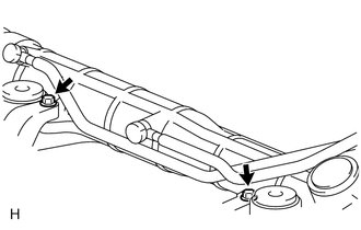
REMOVE POWER STEERING LINK ASSEMBLY
-

Remove the 3 bolts, 3 nuts and power steering link.
-