STEERING LOCK SYSTEM Steering Lock Motor Drive Power Circuit
DESCRIPTION
The main body ECU supplies the power to activate the motor of the steering lock actuator assembly.
The diagnosis information of the steering lock ECU is transmitted to the intelligent tester via the certification ECU (smart key ECU assembly) as the steering lock ECU is not connected to the CAN communication system.
WIRING DIAGRAM
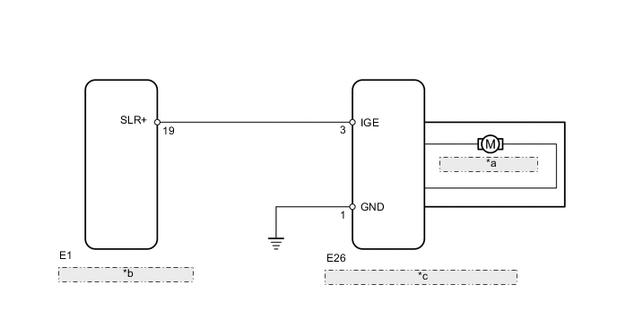
| *a | Steering Lock Motor |
| *b | Main Body ECU (Cowl Side Junction Block LH) |
| *c | Steering Lock Actuator Assembly (Steering Lock ECU) |
CAUTION / NOTICE / HINT
Tech Tips
When the engine switch is off, the main body ECU may occasionally go into a non-active state called sleep mode. Therefore, before proceeding with the inspection, it is necessary to perform the following steps to wake up the ECU:
With the engine switch off, open the driver door. Then (with the engine switch still off) open and close any door several times at 1.5 second intervals.
Note
If the steering lock actuator assembly (steering lock ECU) is replaced, with the engine switch off and the shift lever in P (for A/T), open and close the driver side door to record the current lock position into the steering lock ECU. If this is not performed, the engine may not start.
PROCEDURE
-
CHECK VEHICLE CONDITION
-
Check the problem symptom of the steering lock system.
Result Result Proceed to Steering lock cannot be released A Steering lock cannot lock B
B 
INSPECT STEERING LOCK ECU Click here
A 
-
-
READ VALUE USING INTELLIGENT TESTER (LOCK/UNLOCK RECEIVE)
-
Use the Data List to check if the steering lock command is functioning properly.
Entry&Start Tester Display Measurement Item/Range Normal Condition Diagnostic Note Lock/Unlock Receive Steering lock command reception record/YES or NO YES: Steering lock/unlock signal received
NO: Steering lock/unlock signal not received
- OK YES is displayed on the intelligent tester screen.
NG 
GO TO ENTRY AND START SYSTEM (FOR START FUNCTION) (HOW TO PROCEED WITH TROUBLESHOOTING) Click here
OK
-
-
INSPECT STEERING LOCK ECU
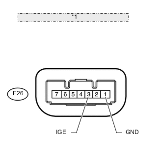
*1 Component with harness connected: (Steering Lock ECU)
-
Immediately after turning the engine switch on (IG), measure the voltage between terminals E26-3 (IGE) and E26-1 (GND) of the steering lock ECU.
Result Result Proceed to 11 to 14 V (measured voltage never becomes below 1 V) A Below 1 V B
B
GO TO ENTRY AND START SYSTEM (FOR START FUNCTION) (PROBLEM SYMPTOMS TABLE) Click here
A
-
-
CHECK HARNESS AND CONNECTOR (STEERING LOCK ECU - MAIN BODY ECU)
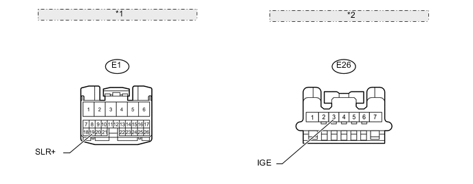
*1 Front view of wire harness connector: (to Main Body ECU) *2 Front view of wire harness connector: (to Steering Lock ECU)
-
Disconnect the E26 steering lock ECU connector.
-
Disconnect the E1 main body ECU connector.
-
Measure the resistance according to the value(s) in the table below.
Standard Resistance Tester Connection Condition Specified Condition E26-3 (IGE) - E1-19 (SLR+) Always Below 1 Ω E26-3 (IGE) or E1-19 (SLR+) - Body ground Always 10 kΩ or higher
OK
REPLACE MAIN BODY ECU
NG
REPAIR OR REPLACE HARNESS OR CONNECTOR
-
-
INSPECT STEERING LOCK ECU
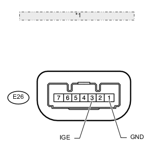
*1 Component with harness connected: (Steering Lock ECU)
-
Move the shift lever to P (for A/T).
-
Turn the engine switch off.
-
Open the driver side door.
-
Measure the voltage according to the value(s) in the table below.
Standard Voltage Tester Connection Condition Specified Condition E26-3 (IGE) - E26-1 (GND) Steering lock motor operating Below 1 V E26-3 (IGE) - E26-1 (GND) Steering lock motor not operating 11 to 14 V
OK
GO TO ENTRY AND START SYSTEM (FOR START FUNCTION) (PROBLEM SYMPTOMS TABLE) Click here
NG
-
-
CHECK HARNESS AND CONNECTOR (STEERING LOCK ECU - MAIN BODY ECU)
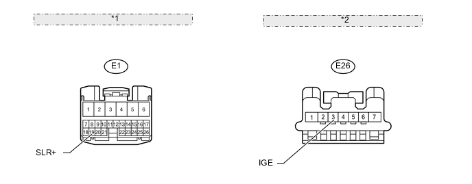
*1 Front view of wire harness connector: (to Main Body ECU) *2 Front view of wire harness connector: (to Steering Lock ECU)
-
Disconnect the E26 steering lock ECU connector.
-
Disconnect the E1 main body ECU connector.
-
Measure the resistance according to the value(s) in the table below.
Standard Resistance Tester Connection Condition Specified Condition E26-3 (IGE) - E1-19 (SLR+) Always Below 1 Ω E26-3 (IGE) or E1-19 (SLR+) - Body ground Always 10 kΩ or higher
OK
REPLACE MAIN BODY ECU
NG
REPAIR OR REPLACE HARNESS OR CONNECTOR
-