POWER TILT AND POWER TELESCOPIC STEERING COLUMN SYSTEM IG Power Source Circuit
DESCRIPTION
When the engine switch is turned on (IG), the IG power source circuit supplies positive (+) voltage to the multiplex tilt and telescopic ECU.
WIRING DIAGRAM
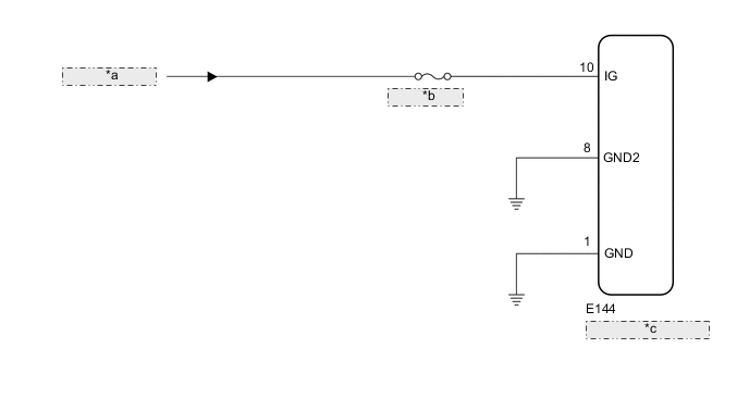
| *a | from IG Circuit |
| *b | ECU-IG NO. 2 |
| *c | Multiplex Tilt and Telescopic ECU |
CAUTION / NOTICE / HINT
Tech Tips
Inspect the fuses for circuits related to this system before performing the following inspection procedure.
PROCEDURE
-
CHECK HARNESS AND CONNECTOR (MULTIPLEX TILT AND TELESCOPIC ECU - BATTERY)
-
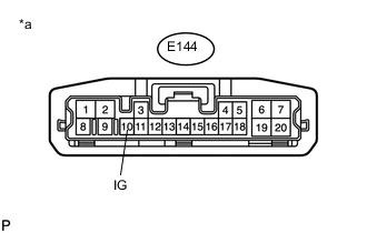
Text in Illustration *a Front view of wire harness connector
(to Multiplex Tilt and Telescopic ECU)
Disconnect the multiplex tilt and telescopic ECU connector.
-
Measure the voltage according to the value(s) in the table below.
Standard Voltage Tester Connection Switch Condition Specified Condition E144-10 (IG) - Body ground Engine switch on (IG) 11 to 14 V
NG 
REPAIR OR REPLACE HARNESS OR CONNECTOR
OK 
-
-
CHECK HARNESS AND CONNECTOR (MULTIPLEX TILT AND TELESCOPIC ECU - BODY GROUND)
-
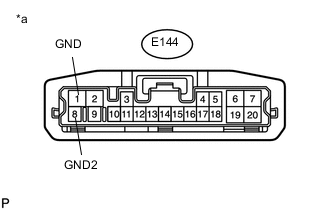
Text in Illustration *a Front view of wire harness connector
(to Multiplex Tilt and Telescopic ECU)
Disconnect the multiplex tilt and telescopic ECU connector.
-
Measure the resistance according to the value(s) in the table below.
Standard Resistance Tester Connection Condition Specified Condition E144-1 (GND) - Body ground Always Below 1 Ω E144-8 (GND2) - Body ground
OK
REPLACE MULTIPLEX TILT AND TELESCOPIC ECU Click here
NG
REPAIR OR REPLACE HARNESS OR CONNECTOR
-