VARIABLE GEAR RATIO STEERING SYSTEM, Diagnostic DTC:C15A3/63, C15C5/69

| DTC Code | DTC Name |
|---|---|
| C15A3/63 | Motor Rotation Angle Not Detected |
| C15C5/69 | Motor Rotation Signal Not Detected |
DESCRIPTION
The steering actuator assembly drives the internal motor using the current output from the VGRS ECU (steering control ECU) to change the relative angle between the tire angle and steering wheel angle.
The motor rotation angle sensor in the steering actuator assembly detects the motor rotation angle and outputs this information to the VGRS ECU (steering control ECU).
If the VGRS ECU (steering control ECU) detects a malfunction in the motor rotation angle sensor circuit, it stores DTC C15A3/63.
The test mode DTC C15C5/69 is only stored during test mode.
| DTC No. | DTC Detection Condition | Trouble Area |
|---|---|---|
| C15A3/63 | All conditions are met for approximately 0.03 seconds or more:
|
|
| C15C5/69 | The system enters test mode. |
|
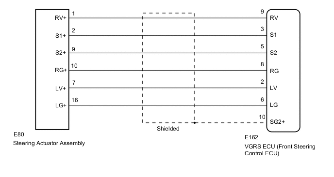
WIRING DIAGRAM
CAUTION / NOTICE / HINT
Note
-
When replacing the VGRS ECU (steering control ECU) or steering actuator assembly, perform actuator angle neutral point calibration and initialization after replacing parts Click here.
-
Since DTC C1289 is stored in the skid control ECU (master cylinder solenoid), after performing repairs on the VGRS system, clear the DTCs for the vehicle stability control system.
PROCEDURE
-
CHECK DTC
-
Check for DTCs Click here.
Result Result Proceed to
-
DTC C15A3/63 is output as a current DTC
-
When the engine is started and the steering wheel is operated, DTC C15A3/63 is output as a current DTC.
A When the engine is started and a wire harness is jiggled, DTC C15A3/63 is output as a current DTC. B DTC C15A3/63 is not output as a current DTC C -
B 
REPAIR OR REPLACE HARNESS OR CONNECTOR
C
USE SIMULATION METHOD TO CHECK Click here
A 
-
-
CHECK FRAME DATA (MOTOR RESOLVER SIN PHASE OFFSET,MOTOR RESOLVER COS PHASE OFFSET)
-
Turn the engine switch off.
-
Connect the GTS to the DLC3.
-
Turn the engine switch on (IG).
-
Turn the GTS on.
-
Display the DTCs on the GTS screen Click here.
-
Select DTC "C15A3/63", and check the freeze frame data for "Motor Resolver SIN Phase Offset" and "Motor Resolver COS Phase Offset" Click here.
Result Result Proceed to "Motor Resolver SIN Phase Offset" and "Motor Resolver COS Phase Offset" are 5 V or higher A "Motor Resolver SIN Phase Offset" and "Motor Resolver COS Phase Offset" are below 5 V (for LHD) B "Motor Resolver SIN Phase Offset" and "Motor Resolver COS Phase Offset" are below 5 V (for RHD) C
B
REPLACE VGRS ECU (STEERING CONTROL ECU) Click here
C
REPLACE VGRS ECU (STEERING CONTROL ECU) Click here
A
-
-
INSPECT STEERING ACTUATOR ASSEMBLY
-
Turn the engine switch off.
-
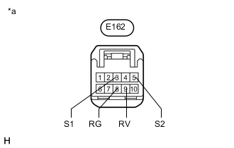
Text in Illustration *a Front view of wire harness connector
(to VGRS ECU [Steering Control ECU])
Disconnect the E162 VGRS ECU (steering control ECU) connector.
-
Measure the resistance according to the value(s) in the table below.
Tech Tips
Measure the resistance of the steering actuator assembly at the connector of the VGRS ECU (steering control ECU).
Standard Resistance Tester Connection Condition Specified Condition E162-9 (RV) - E162-8 (RG) Always 20 to 60 Ω E162-3 (S1) - E162-8 (RG) Always 70 to 160 Ω E162-5 (S2) - E162-8 (RG) Always 60 to 150 Ω E162-9 (RV) - E162-3 (S1) Always 90 to 220 Ω E162-9 (RV) - E162-5 (S2) Always 80 to 210 Ω E162-3 (S1) - E162-5 (S2) Always 130 to 310 Ω E162-3 (S1) - Body ground Always 100 kΩ or higher E162-5 (S2) - Body ground Always 100 kΩ or higher E162-8 (RG) - Body ground Always 100 kΩ or higher E162-9 (RV) - Body ground Always 100 kΩ or higher Result Result Proceed to OK (for LHD) A OK (for RHD) B NG C
A
REPLACE VGRS ECU (STEERING CONTROL ECU) Click here
B
REPLACE VGRS ECU (STEERING CONTROL ECU) Click here
C
-
-
CHECK HARNESS AND CONNECTOR (VGRS ECU (STEERING CONTROL ECU) - STEERING ACTUATOR ASSEMBLY)
-
Turn the engine switch off.
-
Disconnect the E162 VGRS ECU (steering control ECU) connector.
-
Disconnect the E80 steering actuator assembly connector.
-
Measure the resistance according to the value(s) in the table below.
Standard Resistance Tester Connection Condition Specified Condition E162-3 (S1) - E80-2 (S1+) Always Below 1 Ω E162-5 (S2) - E80-9 (S2+) Always Below 1 Ω E162-8 (RG) - E80-10 (RG+) Always Below 1 Ω E162-9 (RV) - E80-1 (RV+) Always Below 1 Ω E162-9 (RV) - E162-8 (RG) Always 20 to 60 Ω E162-3 (S1) - E162-8 (RG) Always 70 to 160 Ω E162-5 (S2) - E162-8 (RG) Always 60 to 150 Ω E162-9 (RV) - E162-3 (S1) Always 90 to 220 Ω E162-9 (RV) - E162-5 (S2) Always 80 to 210 Ω E162-3 (S1) - E162-5 (S2) Always 130 to 310 Ω E162-3 (S1) or E80-2 (S1+) - Body ground Always 100 kΩ or higher E162-5 (S2) or E80-9 (S2+) - Body ground Always 100 kΩ or higher E162-8 (RG) or E80-10 (RG+) - Body ground Always 100 kΩ or higher E162-9 (RV) or E80-1 (RV+) - Body ground Always 100 kΩ or higher
OK
REPLACE STEERING ACTUATOR ASSEMBLY Click here
NG
REPAIR OR REPLACE HARNESS OR CONNECTOR
-