VARIABLE GEAR RATIO STEERING SYSTEM TEST MODE PROCEDURE

-
TEST MODE (VGRS SENSOR SIGNAL CHECK)
Tech Tips
-
When the system enters test mode, "VGRS Test Mode" is displayed on the multi-information display.
-
Before entering test mode, check and repair any malfunctions indicated by the present DTCs of the VGRS system.
-
By switching from normal mode to test mode, the steering angle sensor can be read.
-
When entering test mode, the steering control ECU sets all the test mode DTCs first.
-
When the mode is switched from test mode to normal mode, all the test mode DTCs will be cleared.
-
Procedure to enter Test Mode (using GTS)
-
Turn the engine switch off.
-
Connect the GTS to the DLC3.
-
Turn the engine switch on (IG).
-
Turn the GTS on.
-
Enter the following menus: Chassis / VGRS / Utility / Signal Check.
-
-
Procedure to enter Test Mode (using SST check wire)
-
Turn the engine switch off.
-
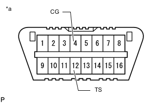
*a Front view of DLC3 Using SST, connect terminals 12 (TS) and 4 (CG) of the DLC3.
- SST
- 09843-18040
-
Turn the engine switch on (IG).
-
-
Check the Test Mode display.
-
Check that "VGRS TEST MODE" is displayed on the multi-information display when the system enters Test Mode.
-
-
Check the steering sensor signal and motor rotation signal.
-
Start the engine.
-
Rotate the steering wheel slowly from lock to lock.
Tech Tips
-
The state of the master warning light does not change.
-
When the steering signal is confirmed to be normal, the test mode DTC C15C4/68 is cleared.
-
When the steering sensor zero point calibration is performed and the motor rotation signal is confirmed to be normal, the test mode DTC C15C5/69 is cleared.
-
-
-
Read Test Mode DTCs (using GTS)
-
Read the test mode DTCs by following the prompts on the GTS screen.
-
-
Read Test Mode DTCs (using SST check wire)
Note
Perform these procedures with the vehicle stopped.
-
Turn the engine switch off.
-
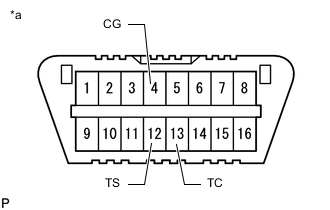
*a Front view of DLC3 Using SST, connect terminals 12 (TS), 13 (TC) and 4 (CG) of the DLC3.
- SST
- 09843-18040
-
Turn the engine switch on (IG).
-
Read the 2-digit test mode DTCs from the multi-information display.
-
-
Clear Test Mode DTCs (using GTS)
-
After completing test mode, disconnect the GTS and turn the engine switch off.
-
-
Clear the test mode DTCs (using SST check wire).
-
Turn the engine switch off.
-
Disconnect SST from the DLC3.
- SST
- 09843-18040
-
Turn the engine switch on (IG).
Tech Tips
If the engine switch is turned on (IG) with terminals 12 (TS) and 4 (CG) connected, the system remains in test mode.
-
-
-
TEST MODE DTC
-
If a trouble code is displayed during the DTC check, check the circuit indicated by the DTC. For details of each code, proceed to the DTC chart.
DTC Code Detection Item Trouble Area Proceed to C15C4/68 A steering signal indicating a tire angle of 36° or more (to the left or right) is input after entering test mode*
-
Steering angle sensor
-
Harness or connector
-
Steering control ECU
C15C5/69 A steering signal indicating a motor rotation angle of 36° or more (to the left or right) is input after entering test mode*
-
Harness or connector
-
Steering actuator
-
Steering control ECU
Tech Tips
*: A tire angle of 36° and a motor rotation angle of 36° correspond to the steering wheel angle. The amount of change in tire angle and motor rotation angle is from when the mode is changed to test mode.
-
-