VANE PUMP(for 1UR-FE) REASSEMBLY

CAUTION / NOTICE / HINT
Note
When installing parts, coat the parts indicated by arrows with power steering fluid Click here.
PROCEDURE
-
INSTALL VANE PUMP HOUSING OIL SEAL
-
Coat the lip of a new oil seal with power steering fluid.
-
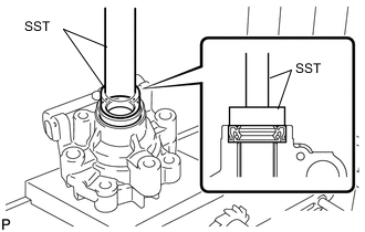
Using SST and a press, press in the oil seal.
- SST
- 09950-60010 ( 09951-00280 )
- 09950-70010 ( 09951-07100 )
Note
Make sure that the oil seal is installed facing in the correct direction as shown in the illustration.
-
-
INSTALL VANE PUMP SHAFT WITH VANE PUMP PULLEY
-
Coat the inside surface of the bushing in the vane pump front housing with power steering fluid.
-
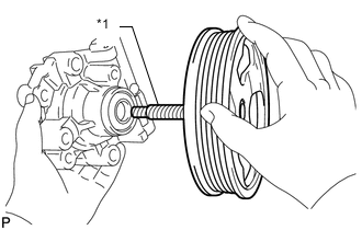
Text in Illustration *1 Protective Tape Gradually insert the vane pump shaft with vane pump pulley.
Note
-
Do not damage the lip of the oil seal in the front housing.
-
Wrap protective tape around the spline of the vane pump shaft with vane pump pulley in order to prevent damage to the oil seal.
-
-
-
INSTALL VANE PUMP FRONT SIDE PLATE
-
Coat a new O-ring with power steering fluid and install it into the front housing.
-
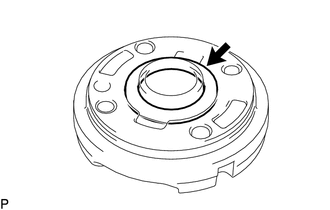
Coat a new O-ring with power steering fluid and install it onto the front side plate.
-
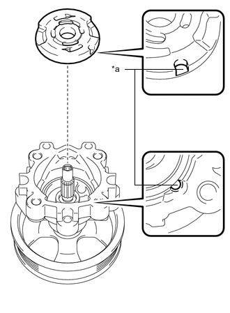
Text in Illustration *a Align Align the notch of the front side plate with the notch of the front housing, and install the front side plate.
Note
Make sure that the front side plate is installed facing in the correct direction.
-
-
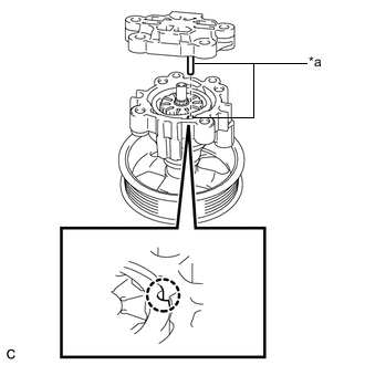
INSTALL VANE PUMP CAM RING
-
Coat the vane pump cam ring with power steering fluid.
-
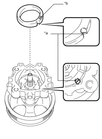
Text in Illustration *a Align *b Inscribed Mark Align the notch of the cam ring with the notch of the front side plate, and install the cam ring with the inscribed mark facing upward.
Note
Make sure that the cam ring is installed facing in the correct direction.
-
-
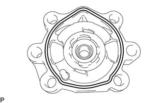
INSTALL VANE PUMP ROTOR
-
Coat the vane pump rotor with power steering fluid.
-
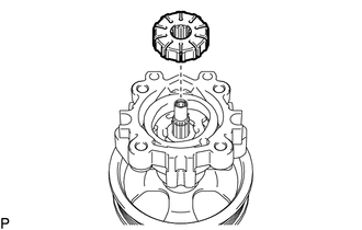
Install the vane pump rotor.
Tech Tips
The vane pump rotor can be installed in both directions.
-
Coat the 10 vane pump plates with power steering fluid.
-
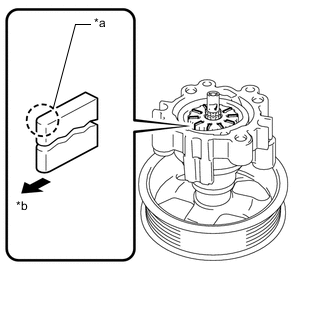
Text in Illustration *a Round End *b Outward Install the vane pump plates with the round end facing outward.
Note
Make sure that the vane pump plates are installed facing in the correct direction.
-
-
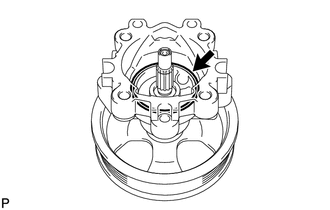
INSTALL VANE PUMP SHAFT SNAP RING
-
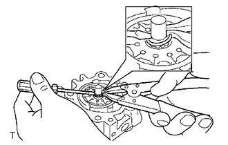
Using a screwdriver and snap ring expander, install a new shaft snap ring onto the vane pump shaft.
Note
-
Do not expand the shaft snap ring any further than needed.
-
Make sure that the shaft snap ring is completely fit into the groove.
-
Do not damage the vane pump rotor and shaft.
-
-
-
INSTALL VANE PUMP REAR HOUSING (w/o Variable Flow Control Solenoid Valve)
-
Coat a new O-ring with power steering fluid and install it onto the rear housing.
-
Text in Illustration *a Align Align the straight pin of the rear housing with the notches of the cam ring, front side plate and front housing.
Note
Make sure that the O-ring is not protruding anywhere when installing the vane pump rear housing.
-
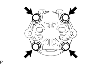
Install the rear housing with the 4 bolts.
- Torque:
- 22 N*m { 224 kgf*cm, 16 ft.*lbf }
-
-
INSTALL VANE PUMP REAR HOUSING (w/ Variable Flow Control Solenoid Valve)
-
Coat a new O-ring with power steering fluid and install it onto the rear housing.
-
Text in Illustration *a Align Align the straight pin of the rear housing with the notches of the cam ring, front side plate and front housing.
Note
Make sure that the O-ring is not protruding anywhere when installing the vane pump rear housing.
-
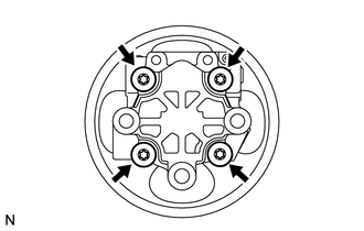
Install the rear housing with the 4 "Torx" bolts.
- Torque:
- 22 N*m { 224 kgf*cm, 16 ft.*lbf }
-
-
INSPECT TOTAL PRELOAD
-
INSTALL FLOW CONTROL VALVE ASSEMBLY (w/o Variable Flow Control Solenoid Valve)
-
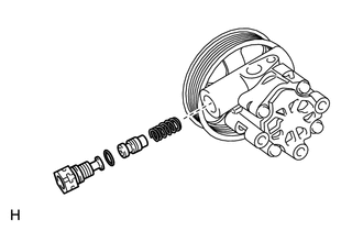
Coat the flow control valve, pressure port union and spring with power steering fluid.
-
Install the compression spring and flow control valve to the front housing.
Note
Do not mistake the direction of the control valve.
-
Coat a new O-ring with power steering fluid and install it onto the pressure port union.
-
Install the pressure port union to the front housing.
- Torque:
- 69 N*m { 704 kgf*cm, 51 ft.*lbf }
-
-
FIX VANE PUMP ASSEMBLY
-
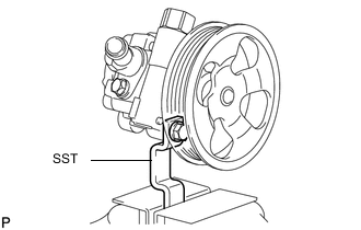
Using SST, fix the vane pump in a vise.
- SST
- 09630-00014 ( 09631-00132 )
-
-
INSTALL POWER STEERING SUCTION PORT UNION (w/o Variable Flow Control Solenoid Valve)
-
Coat a new O-ring with power steering fluid and install it to the suction port union.
-
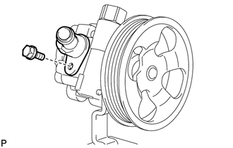
Install the suction port union to the vane pump with the bolt.
- Torque:
- 12 N*m { 122 kgf*cm, 9 ft.*lbf }
-