DECELERATION SENSOR(w/ ABS) INSTALLATION
PROCEDURE
-
INSTALL DECELERATION SENSOR (for Automatic Transmission)
-
Connect the sensor connector, and then attach the clamp to the hole of the sensor bracket.
Note
Securely connect the connector.
-
Install the sensor with the 2 bolts.
- Torque:
- 15 N*m { 148 kgf*cm, 11 ft.*lbf }
Note
-
Make sure that the sensor is oriented correctly.
-
If the sensor is dropped, replace it.
-
When installing the sensor, make sure to avoid impacts to the sensor.
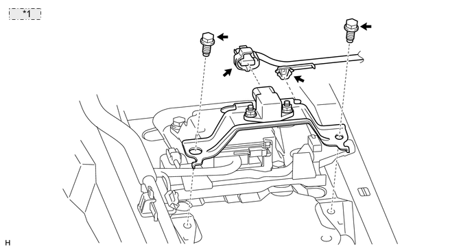
*1 for LHD: 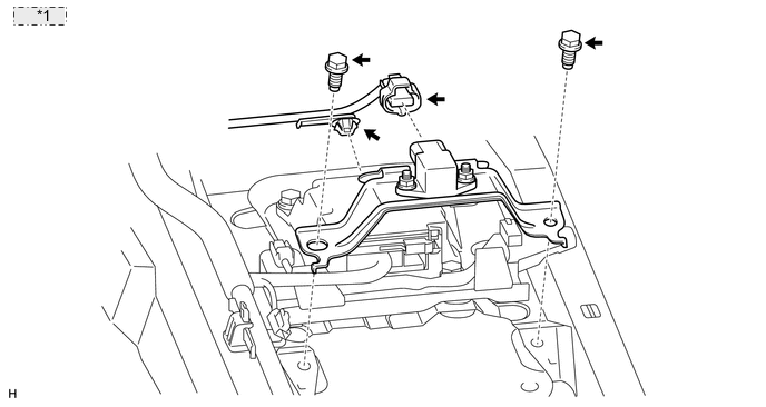
*1 for RHD:
-
-
INSTALL DECELERATION SENSOR (for Manual Transmission)
-
Connect the sensor connector, and then attach the clamp to the hole of the sensor bracket.
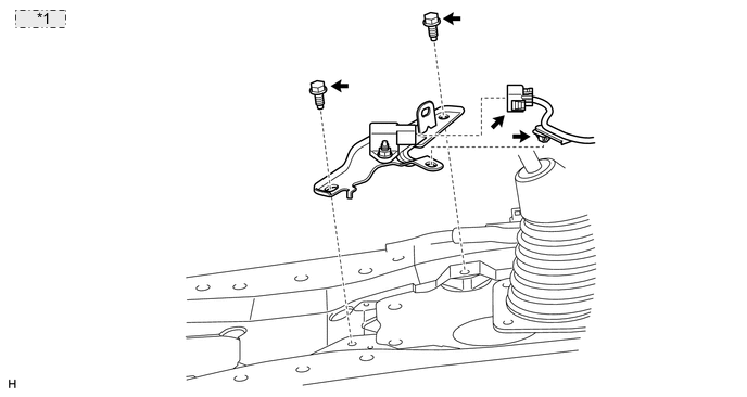
*1 for LHD: 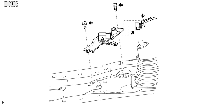
*1 for RHD: -
Install the sensor with the 2 bolts.
- Torque:
- 15 N*m { 148 kgf*cm, 11 ft.*lbf }
Note
-
Make sure that the sensor is oriented correctly.
-
If the sensor is dropped, replace it.
-
Securely connect the connector.
-
When installing the sensor, make sure to avoid impacts to the sensor.
-
-
INSTALL LOWER CONSOLE BOX (w/o Console Box Lid)
-
INSTALL COOLING BOX ASSEMBLY (w/ Cool Box)
-
INSTALL REAR CONSOLE BOX SUB-ASSEMBLY (w/o Cool Box)
-
CONNECT CABLE TO NEGATIVE BATTERY TERMINAL
Note
When disconnecting the cable, some systems need to be initialized after the cable is reconnected Click here.
-
PERFORM G SENSOR ZERO POINT CALIBRATION
-
Perform the G sensor zero point calibration Click here.
-
-
CHECK G SENSOR SIGNAL
-
Check the G sensor signal Click here.
-