VEHICLE STABILITY CONTROL SYSTEM Skid Control Buzzer Circuit
DESCRIPTION
The skid control buzzer sounds upon receiving a signal from the skid control ECU (master cylinder solenoid).
WIRING DIAGRAM
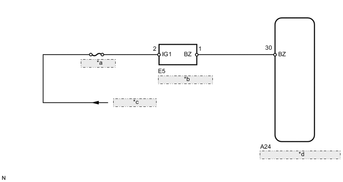
| *a | ECU-IG No. 1 |
| *b | Skid Control Buzzer |
| *c | from IG Circuit |
| *d | Skid Control ECU (Master Cylinder Solenoid) |
CAUTION / NOTICE / HINT
Note
-
After replacing the master cylinder solenoid, perform zero point calibration and store the system information Click here.
-
Inspect the fuses for circuits related to this system before performing the following inspection procedure.
PROCEDURE
-
PERFORM ACTIVE TEST USING GTS (DSS SIGNAL BUZZER)
-
Turn the ignition switch off.
-
Connect the GTS to the DLC3.
-
Turn the ignition switch to ON.
-
Turn the GTS on.
-
Enter the following menus: Chassis / ABS/VSC/TRC / Active Test.
ABS/VSC/TRC Tester Display Test Part Control Range Diagnostic Note DSS Signal Buzzer Skid control buzzer Buzzer ON/OFF The buzzer can be heard. -
Check that the skid control buzzer sounds/stops when turning the skid control buzzer on/off by using the GTS.
Result Result Proceed to Buzzer does not sound or sounds constantly A Buzzer sounds/stops B
B 
CHECK FOR INTERMITTENT PROBLEMS Click here
A 
-
-
CHECK TERMINAL VOLTAGE (IG1)
-
Turn the ignition switch off.
-
Disconnect the skid control buzzer assembly connector.
-
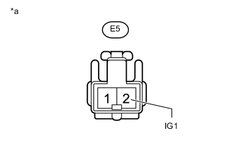
Text in Illustration *a Front view of wire harness connector
(to Skid Control Buzzer Assembly)
Measure the voltage according to the value(s) in the table below.
Standard Voltage Tester Connection Switch Condition Specified Condition E5-2 (IG1) - Body ground Ignition switch ON 11 to 14 V
NG
REPAIR OR REPLACE HARNESS OR CONNECTOR
OK
-
-
INSPECT SKID CONTROL BUZZER
-
Remove the skid control buzzer assembly Click here.
-
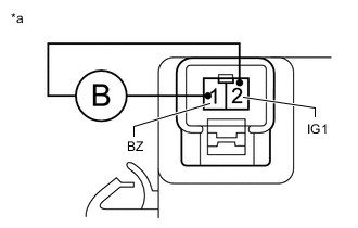
Text in Illustration *a Component without harness connected
(Skid Control Buzzer Assembly)
Apply battery voltage to the skid control buzzer, and check that the buzzer sounds.
OK Measurement Condition Specified Condition Battery positive (+) voltage - Terminal 2 (IG1) Skid control buzzer sounds Battery negative (-) voltage - Terminal 1 (BZ)
NG
REPLACE SKID CONTROL BUZZER ASSEMBLY Click here
OK
-
-
CHECK HARNESS AND CONNECTOR (SKID CONTROL BUZZER - SKID CONTROL ECU)
-
Turn the ignition switch off.
-
Disconnect the A24 skid control ECU (master cylinder solenoid) connector.
-
Disconnect the E5 skid control buzzer assembly connector.
-
Measure the resistance according to the value(s) in the table below.
Standard Resistance Tester Connection Condition Specified Condition A24-30 (BZ) - E5-1 (BZ) Always Below 1 Ω A24-30 (BZ) - Body ground Always 10 kΩ or higher Result Result Proceed to NG A OK (for LHD) B OK (for RHD) C
A
REPAIR OR REPLACE HARNESS OR CONNECTOR
B
REPLACE MASTER CYLINDER SOLENOID Click here
C
REPLACE MASTER CYLINDER SOLENOID Click here
-