VEHICLE STABILITY CONTROL SYSTEM Crawl Indicator Light Remains ON
DESCRIPTION
-
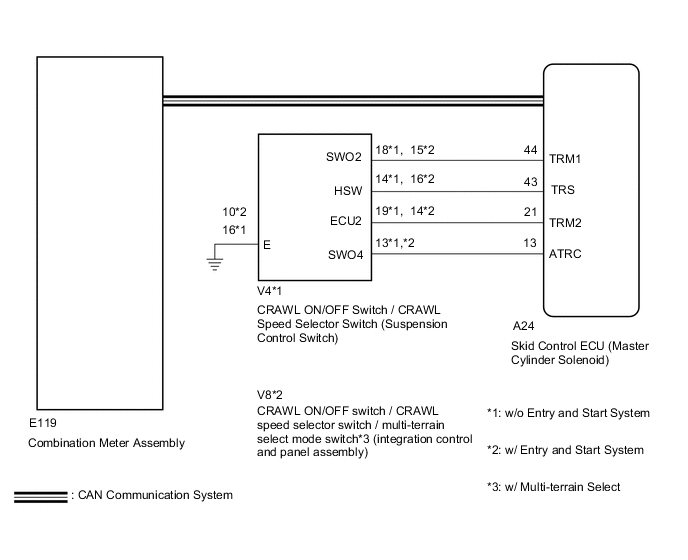
w/o Entry and Start System:
When CRAWL starts after operating the CRAWL ON/OFF switch / CRAWL speed selector switch (suspension control switch), the CRAWL indicator light turns on. While CRAWL is in the process of stopping, the CRAWL indicator light begins blinking. When CRAWL totally stops, the CRAWL indicator light turns off.
-
w/ Entry and Start System:
When CRAWL starts after operating the CRAWL ON/OFF switch / CRAWL speed selector switch / multi-terrain select mode switch* (integration control and panel assembly), the CRAWL indicator light turns on. While CRAWL is in the process of stopping, the CRAWL indicator light begins blinking. When CRAWL totally stops, the CRAWL indicator light turns off.
-
*: w/ Multi-terrain Select
Tech Tips
When crawl control is activated with all of the crawl control activation conditions fulfilled during multi-terrain select control and the accelerator pedal is depressed, the multi-terrain select indicator light and crawl indicator light illuminate and multi-terrain select control enters "AUTO" mode. When the accelerator pedal is released, the multi-terrain select indicator light and crawl indicator light illuminate and crawl control begins.
WIRING DIAGRAM
CAUTION / NOTICE / HINT
Note
After replacing the master cylinder solenoid, perform zero point calibration and store the system information Click here.
PROCEDURE
-
CHECK CAN COMMUNICATION LINE
-
Turn the ignition switch off.
-
Connect the GTS to the DLC3.
-
Turn the ignition switch to ON and the GTS on.
-
Select "CAN Bus Check" from the System Selection Menu screen, and follow the prompts on the screen to inspect the CAN Bus.
OK "CAN Bus Check" indicates no malfunctions in CAN communication. Result Result Proceed to OK A NG (for LHD (with Central Gateway ECU)) B NG (for LHD (without Central Gateway ECU)) C NG (for RHD (with Central Gateway ECU)) D NG (for RHD (without Central Gateway ECU)) E
B 
GO TO CAN COMMUNICATION SYSTEM (HOW TO PROCEED WITH TROUBLESHOOTING) Click here
C
GO TO CAN COMMUNICATION SYSTEM (HOW TO PROCEED WITH TROUBLESHOOTING) Click here
D
GO TO CAN COMMUNICATION SYSTEM (HOW TO PROCEED WITH TROUBLESHOOTING) Click here
E
GO TO CAN COMMUNICATION SYSTEM (HOW TO PROCEED WITH TROUBLESHOOTING) Click here
A 
-
-
CHECK DTC (CAN COMMUNICATION SYSTEM)
-
Turn the ignition switch off.
-
Connect the GTS to the DLC3.
-
Turn the ignition switch to ON and the GTS on.
-
for LHD (with Central Gateway ECU):
Check for DTCs Click here.
-
for LHD (without Central Gateway ECU):
Check for DTCs Click here.
-
for RHD (with Central Gateway ECU):
Check for DTCs Click here.
-
for RHD (without Central Gateway ECU):
Check for DTCs Click here.
Result Result Proceed to CAN DTC is not output A CAN DTC is output (for LHD (with Central Gateway ECU)) B CAN DTC is output (for LHD (without Central Gateway ECU)) C CAN DTC is output (for RHD (with Central Gateway ECU)) D CAN DTC is output (for RHD (without Central Gateway ECU)) E
B
GO TO CAN COMMUNICATION SYSTEM (HOW TO PROCEED WITH TROUBLESHOOTING) Click here
C
GO TO CAN COMMUNICATION SYSTEM (HOW TO PROCEED WITH TROUBLESHOOTING) Click here
D
GO TO CAN COMMUNICATION SYSTEM (HOW TO PROCEED WITH TROUBLESHOOTING) Click here
E
GO TO CAN COMMUNICATION SYSTEM (HOW TO PROCEED WITH TROUBLESHOOTING) Click here
A
-
-
PERFORM ACTIVE TEST USING GTS (CRAWL CONTROL LIGHT)
-
Turn the ignition switch off.
-
Connect the GTS to the DLC3.
-
Turn the ignition switch to ON.
-
Turn the GTS on.
-
Enter the following menus: Chassis / ABS/VSC/TRC / Active Test.
ABS/VSC/TRC Tester Display Test Part Control Range Diagnostic Note Crawl Control Light CRAWL indicator light Indicator light ON/OFF Observe the combination meter assembly. -
When performing the Crawl Control Light Active Test, check Crawl Control Light in the Data List.
ABS/VSC/TRC Tester Display Measurement Item/Range Normal Condition Diagnostic Note Crawl Control Light CRAWL indicator light/ ON or OFF ON: Indicator light on
OFF: Indicator light off
- Result Result Proceed to Data List Display Data List Display when Performing Active Test ON/OFF Operation ON Changes between ON and OFF A Does not change between ON and OFF (for LHD) B Does not change between ON and OFF (for RHD) C OFF Changes between ON and OFF A Does not change between ON and OFF (for LHD) B Does not change between ON and OFF (for RHD) C
A
GO TO METER / GAUGE SYSTEM (HOW TO PROCEED WITH TROUBLESHOOTING) Click here
B
REPLACE MASTER CYLINDER SOLENOID Click here
C
REPLACE MASTER CYLINDER SOLENOID Click here
-