VEHICLE STABILITY CONTROL SYSTEM ABS Warning Light Remains ON
DESCRIPTION
If any of the following is detected, the ABS warning light remains on.
-
The skid control ECU (master cylinder solenoid) connectors are disconnected from the skid control ECU (master cylinder solenoid).
-
There is a malfunction in the skid control ECU (master cylinder solenoid) internal circuit.
-
There is an open in the harness between the combination meter assembly and skid control ECU (master cylinder solenoid).
Tech Tips
There is a case that the GTS cannot be used when the skid control ECU (master cylinder solenoid) is abnormal.
WIRING DIAGRAM
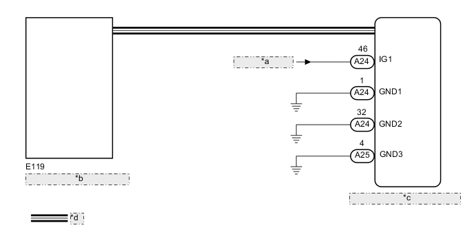
| *a | from IG Circuit |
| *b | Combination Meter Assembly |
| *c | Skid Control ECU (Master Cylinder Solenoid) |
| *d | CAN Communication System |
CAUTION / NOTICE / HINT
Note
After replacing the master cylinder solenoid, perform zero point calibration and store the system information Click here.
PROCEDURE
-
INSPECT IF SKID CONTROL ECU CONNECTOR IS SECURELY CONNECTED
-
Check the skid control ECU (master cylinder solenoid) connector connection.
OK The connector is securely connected.
NG 
CONNECT CONNECTOR TO ECU CORRECTLY
OK 
-
-
INSPECT BATTERY
-
Check the battery voltage.
Standard voltage 11 to 14 V Result Result Proceed to OK A NG (for 1GR-FE) B NG (for 1VD-FTV) C NG (for 1UR-FE) D NG (for 3UR-FE) E
B
GO TO CHARGING SYSTEM (ON-VEHICLE INSPECTION) Click here
C
GO TO CHARGING SYSTEM (ON-VEHICLE INSPECTION) Click here
D
GO TO CHARGING SYSTEM (ON-VEHICLE INSPECTION) Click here
E
GO TO CHARGING SYSTEM (ON-VEHICLE INSPECTION) Click here
A
-
-
CHECK CAN COMMUNICATION LINE
-
Turn the ignition switch off.
-
Connect the GTS to the DLC3.
-
Turn the ignition switch to ON and the GTS on.
-
Select "CAN Bus Check" from the System Selection Menu screen, and follow the prompts on the screen to inspect the CAN Bus.
OK "CAN Bus Check" indicates no malfunctions in CAN communication. Result Result Proceed to OK A NG (for LHD (with Central Gateway ECU)) B NG (for LHD (without Central Gateway ECU)) C NG (for RHD (with Central Gateway ECU)) D NG (for RHD (without Central Gateway ECU)) E
B
GO TO CAN COMMUNICATION SYSTEM (HOW TO PROCEED WITH TROUBLESHOOTING) Click here
C
GO TO CAN COMMUNICATION SYSTEM (HOW TO PROCEED WITH TROUBLESHOOTING) Click here
D
GO TO CAN COMMUNICATION SYSTEM (HOW TO PROCEED WITH TROUBLESHOOTING) Click here
E
GO TO CAN COMMUNICATION SYSTEM (HOW TO PROCEED WITH TROUBLESHOOTING) Click here
A
-
-
CHECK DTC (CAN COMMUNICATION SYSTEM)
-
Turn the ignition switch off.
-
Connect the GTS to the DLC3.
-
Turn the ignition switch to ON and the GTS on.
-
for LHD (with Central Gateway ECU):
Check for DTCs Click here.
-
for LHD (without Central Gateway ECU):
Check for DTCs Click here.
-
for RHD (with Central Gateway ECU):
Check for DTCs Click here.
-
for RHD (without Central Gateway ECU):
Check for DTCs Click here.
Result Result Proceed to CAN DTC is not output A CAN DTC is output (for LHD (with Central Gateway ECU)) B CAN DTC is output (for LHD (without Central Gateway ECU)) C CAN DTC is output (for RHD (with Central Gateway ECU)) D CAN DTC is output (for RHD (without Central Gateway ECU)) E
B
GO TO CAN COMMUNICATION SYSTEM (HOW TO PROCEED WITH TROUBLESHOOTING) Click here
C
GO TO CAN COMMUNICATION SYSTEM (HOW TO PROCEED WITH TROUBLESHOOTING) Click here
D
GO TO CAN COMMUNICATION SYSTEM (HOW TO PROCEED WITH TROUBLESHOOTING) Click here
E
GO TO CAN COMMUNICATION SYSTEM (HOW TO PROCEED WITH TROUBLESHOOTING) Click here
A
-
-
PERFORM ACTIVE TEST USING GTS (INDICAT. LAMP ABS)
-
Turn the ignition switch off.
-
Connect the GTS to the DLC3.
-
Turn the ignition switch to ON and the GTS on.
-
Enter the following menus: Body Electrical / Combination Meter / Active Test.
-
Check the condition of the ABS warning light by operating the GTS.
Combination Meter Tester Display Test Part Control Range Diagnostic Note Indicat. Lamp ABS ABS Warning Light ON or OFF Perform the test with the vehicle stopped and engine idling. OK The warning light turns on or off when operating the GTS.
NG
GO TO METER / GAUGE SYSTEM (HOW TO PROCEED WITH TROUBLESHOOTING) Click here
OK
-
-
CHECK HARNESS AND CONNECTOR (IG1 TERMINAL)
-
Disconnect the skid control ECU (master cylinder solenoid) connector.
-
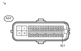
Text in Illustration *a Front view of wire harness connector
(to Skid Control ECU (Master Cylinder Solenoid))
Measure the voltage according to the value(s) in the table below.
Standard Voltage Tester Connection Switch Condition Specified Condition A24-46 (IG1) - Body ground Ignition switch ON 11 to 14 V
NG
REPAIR OR REPLACE HARNESS OR CONNECTOR
OK
-
-
CHECK HARNESS AND CONNECTOR (GND1, GND2 AND GND3 TERMINAL)
-
Turn the ignition switch off.
-
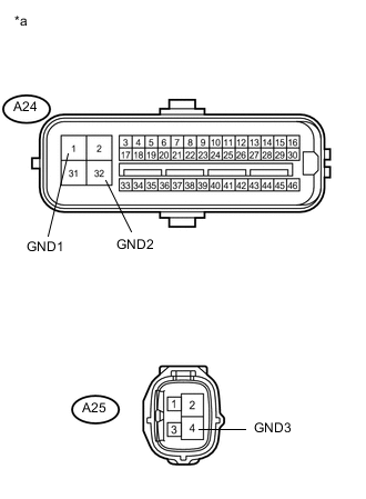
Text in Illustration *a Front view of wire harness connector
(to Skid Control ECU [Master Cylinder Solenoid])
Disconnect the skid control ECU (master cylinder solenoid) connectors.
-
Measure the resistance according to the value(s) in the table below.
Standard Resistance Tester Connection Condition Specified Condition A24-1 (GND1) - Body ground Always Below 1 Ω A24-32 (GND2) - Body ground Always Below 1 Ω A25-4 (GND3) - Body ground Always Below 1 Ω Result Result Proceed to NG A OK (for LHD) B OK (for RHD) C
A
REPAIR OR REPLACE HARNESS OR CONNECTOR
B
REPLACE MASTER CYLINDER SOLENOID Click here
C
REPLACE MASTER CYLINDER SOLENOID Click here
-