VEHICLE STABILITY CONTROL SYSTEM, Diagnostic DTC:C1425
| DTC Code | DTC Name |
|---|---|
| C1425 | Open in Stop Light Switch Circuit |
DESCRIPTION
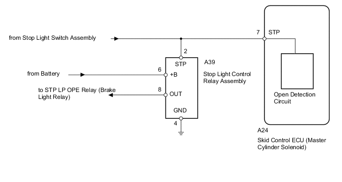
The skid control ECU (master cylinder solenoid) has an open detection circuit, which stores this DTC when detecting an open in the stop light switch input line or the ground line of the stop light switch circuit with the stop light switch off (brake pedal not depressed).
| DTC Code | DTC Detection Condition | Trouble Area |
|---|---|---|
| C1425 | When the IG1 terminal voltage is between 9.5 and 17.4 V and the skid control ECU STPO terminal output is off, an open in the stop light switch circuit continues for 3 seconds or more. |
|
WIRING DIAGRAM
CAUTION / NOTICE / HINT
Note
After replacing the master cylinder solenoid, perform zero point calibration and store the system information Click here.
PROCEDURE
-
READ VALUE USING GTS (STOP LIGHT SW)
-
Turn the ignition switch off.
-
Connect the GTS to the DLC3.
-
Turn the ignition switch to ON.
-
Turn the GTS on.
-
Enter the following menus: Chassis / ABS/VSC/TRC / Data List.
ABS/VSC/TRC Tester Display Measurement Item/Range Normal Condition Diagnostic Note Stop Light SW Stop light switch / ON or OFF ON: Brake pedal depressed
OFF: Brake pedal released
- -
Check that the stop light switch condition observed on the GTS changes according to brake pedal operation.
OK The GTS displays ON and OFF according to brake pedal operation.
NG 
CHECK HARNESS AND CONNECTOR (STP TERMINAL) Click here
OK 
-
-
RECONFIRM DTC
-
Clear the DTCs Click here.
-
Turn the ignition switch off.
-
Start the engine.
-
Depress the brake pedal several times to test the stop light circuit.
-
Check if the same DTC is output Click here.
Result Result Proceed to DTC is not output A DTC is output (for LHD) B DTC is output (for RHD) C
A 
CHECK FOR INTERMITTENT PROBLEMS Click here
B
REPLACE MASTER CYLINDER SOLENOID Click here
C
REPLACE MASTER CYLINDER SOLENOID Click here
-
-
CHECK HARNESS AND CONNECTOR (STP TERMINAL)
-
Turn the ignition switch off.
-
Disconnect the skid control ECU (master cylinder solenoid) connector.
-
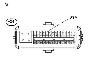
Text in Illustration *a Front view of wire harness connector
(to Skid Control ECU [Master Cylinder Solenoid])
Measure the voltage according to the value(s) in the table below.
Standard Voltage Tester Connection Condition Specified Condition A24-7 (STP) - Body ground Brake pedal depressed 8 to 14 V Brake pedal released Below 1.5 V
NG
REPAIR OR REPLACE HARNESS OR CONNECTOR
OK
-
-
CHECK HARNESS AND CONNECTOR (+B/GND TERMINAL)
-
Turn the ignition switch off.
-
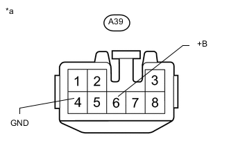
Text in Illustration *a Front view of wire harness connector
(to Stop Light Control Relay Assembly)
Disconnect the stop light control relay assembly connector.
-
Measure the voltage according to the value(s) in the table below.
Standard Voltage Tester Connection Switch Condition Specified Condition A39-6 (+B) - Body ground Always 11 to 14 V -
Measure the resistance according to the value(s) in the table below.
Standard Resistance Tester Connection Condition Specified Condition A39-4 (GND) - Body ground Always Below 1 Ω
NG
REPAIR OR REPLACE HARNESS OR CONNECTOR
OK
-
-
CHECK HARNESS AND CONNECTOR (STP TERMINAL)
-
Turn the ignition switch off.
-
Disconnect the skid control ECU (master cylinder solenoid) connector.
-
Text in Illustration *a Front view of wire harness connector
(to Skid Control ECU [Master Cylinder Solenoid])
Measure the voltage according to the value(s) in the table below.
Standard Voltage Tester Connection Condition Specified Condition A24-7 (STP) - Body ground Brake pedal depressed 8 to 14 V Brake pedal released Below 1.5 V
NG
REPAIR OR REPLACE HARNESS OR CONNECTOR
OK
-
-
CHECK HARNESS AND CONNECTOR (OUT TERMINAL)
-
Reconnect the stop light control relay assembly connector.
-
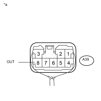
Text in Illustration *a Component with harness connected
(Stop Light Control Relay Assembly)
Measure the voltage according to the value(s) in the table below.
Standard Voltage Tester Connection Condition Specified Condition A39-8 (OUT) - Body ground Brake pedal depressed 8 to 14 V Brake pedal released Below 1.5 V
NG
REPLACE STOP LIGHT CONTROL RELAY ASSEMBLY
OK
-
-
RECONFIRM DTC
-
Clear the DTCs Click here.
-
Turn the ignition switch off.
-
Start the engine.
-
Depress the brake pedal several times to test the stop light circuit.
-
Check if the same DTC is output Click here.
Result Result Proceed to DTC is not output A DTC is output (for LHD) B DTC is output (for RHD) C
A
CHECK FOR INTERMITTENT PROBLEMS Click here
B
REPLACE MASTER CYLINDER SOLENOID Click here
C
REPLACE MASTER CYLINDER SOLENOID Click here
-