VEHICLE STABILITY CONTROL SYSTEM, Diagnostic DTC:C1242
| DTC Code | DTC Name |
|---|---|
| C1242 | Open Circuit in IG1/IG2 Power Source Circuit |
DESCRIPTION
If there is a problem with the skid control ECU (master cylinder solenoid) power supply circuit, the skid control ECU (master cylinder solenoid) stores DTCs and prohibits operation under the fail-safe function.
If the voltage supplied to the IG2 terminal is within the DTC detection range due to malfunctions in components such as the battery and generator circuit, this DTC is stored.
| DTC Code | DTC Detection Condition | Trouble Area |
|---|---|---|
| C1242 | The vehicle speed is 3 km/h (2 mph) or more and the voltage at the ECU IG2 terminal remains below 6.5 V for more than 7 seconds. |
|
WIRING DIAGRAM
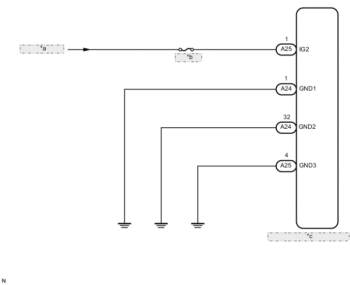
| *a | from IG Circuit |
| *b | IG2 NO. 1 |
| *c | Skid Control ECU (Master Cylinder Solenoid) |
CAUTION / NOTICE / HINT
Note
-
After replacing the master cylinder solenoid, perform zero point calibration and store the system information Click here.
-
Inspect the fuses for circuits related to this system before performing the following inspection procedure.
PROCEDURE
-
CHECK HARNESS AND CONNECTOR (IG2 TERMINAL)
-
Turn the ignition switch off.
-
Disconnect the skid control ECU (master cylinder solenoid) connector.
-
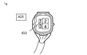
Text in Illustration *a Front view of wire harness connector
(to Skid Control ECU [Master Cylinder Solenoid])
Measure the voltage according to the value(s) in the table below.
Standard Voltage Tester Connection Switch Condition Specified Condition A25-1 (IG2) - Body ground Ignition switch ON 11 to 14 V
NG 
REPAIR OR REPLACE HARNESS OR CONNECTOR
OK 
-
-
CHECK HARNESS AND CONNECTOR (GND1, GND2 AND GND3 TERMINAL)
-
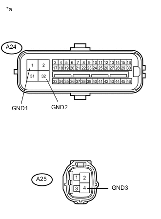
Text in Illustration *a Front view of wire harness connector
(to Skid Control ECU [Master Cylinder Solenoid])
Turn the ignition switch off.
-
Disconnect the skid control ECU (master cylinder solenoid) connectors.
-
Measure the resistance according to the value(s) in the table below.
Standard Resistance Tester Connection Condition Specified Condition A24-1 (GND1) - Body ground Always Below 1 Ω A24-32 (GND2) - Body ground Always Below 1 Ω A25-4 (GND3) - Body ground Always Below 1 Ω
NG
REPAIR OR REPLACE HARNESS OR CONNECTOR
OK
-
-
RECONFIRM DTC
-
Clear the DTCs Click here.
-
Turn the ignition switch off.
-
Check if the same DTC is output Click here.
Tech Tips
Reinstall the sensors, connectors, etc. and restore the previous vehicle conditions before rechecking for DTCs.
Result Result Proceed to DTC is not output A DTC is output (for LHD) B DTC is output (for RHD) C
A
CHECK FOR INTERMITTENT PROBLEMS Click here
B
REPLACE MASTER CYLINDER SOLENOID Click here
C
REPLACE MASTER CYLINDER SOLENOID Click here
-