VEHICLE STABILITY CONTROL SYSTEM TERMINALS OF ECU
-
TERMINALS OF ECU
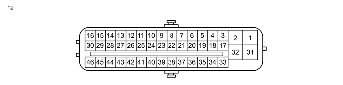
Text in Illustration *a Component without harness connected
(Skid Control ECU [Master Cylinder Solenoid])
- - Terminal No. (Symbol) Terminal Description 1 (GND1) Skid control ECU (Master cylinder solenoid) ground 2 (+BM1) Power supply for motor 3 (FR+) Front speed sensor RH power supply output 4 (FL-) Front speed sensor LH input 5 (RR+) Rear speed sensor RH power supply output 6 (RL-) Rear speed sensor LH input 7 (STP) Stop light switch assembly 9 (CSW) VSC OFF switch*1 VSC OFF switch (Integration control and panel assembly)*2 11 (CANH) CAN communication terminal H 12 (SP1) Speedometer signal 13 (ATRC) CRAWL speed selector switch (Suspension control switch)*1 CRAWL speed selector switch / multi-terrain select mode switch*3 (Integration control and panel assembly)*2 16 (STPO) STP LP OPE relay (Brake light relay) 17 (FR-) Front speed sensor RH input 18 (FL+) Front speed sensor LH power supply output 19 (RR-) Rear speed sensor RH input 20 (RL+) Rear speed sensor LH power supply output 21 (TRM2) CRAWL speed selector switch (Suspension control switch)*1 CRAWL speed selector switch / multi-terrain select mode switch*3 (Integration control and panel assembly)*2 25 (CANL) CAN communication terminal L 27 (EXI) Center differential lock detection switch (Transfer shift actuator assembly) 29 (EXI4) Turn assist function switch (Integration control and panel assembly) signal 31 (+BS) Power supply for solenoid 32 (GND2) Skid control ECU (Master cylinder solenoid) ground 41 (LBL) Brake fluid level warning switch (Brake master cylinder reservoir sub-assembly) 43 (TRS) CRAWL speed selector switch (Suspension control switch)*1 CRAWL speed selector switch / multi-terrain select mode switch*3 (Integration control and panel assembly)*2 44 (TRM1) CRAWL ON/OFF switch (Suspension control switch)*1 CRAWL ON/OFF switch (Integration control and panel assembly)*2 45 (STP2) STP LP OPE relay (Brake light relay) 46 (IG1) IG1 power supply
-
*1: w/o Entry and Start System
-
*2: w/ Entry and Start System
-
*3: w/ Multi-terrain Select

Text in Illustration *a Component without harness connected
(Skid Control ECU [Master Cylinder Solenoid])
- - Terminal No. (Symbol) Terminal Description 1 (IG2) IG2 power supply 2 (+BM2) Power supply for motor 4 (GND3) Skid control ECU (Master cylinder solenoid) ground -
-
TERMINAL INSPECTION
Disconnect the connector and measure the voltage or resistance on the wire harness side.
Tech Tips
Voltage cannot be measured with the connector connected to the skid control ECU (master cylinder solenoid) as the connector is watertight.
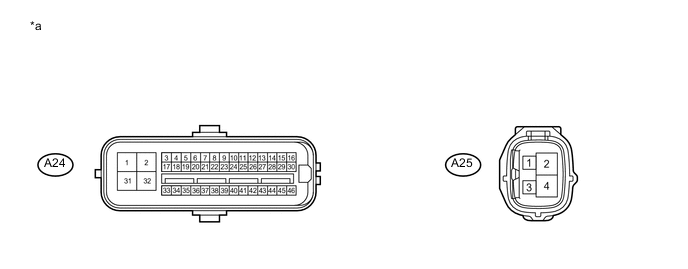
Text in Illustration *a Front view of wire harness connector
(to Skid Control ECU [Master Cylinder Solenoid])
- - Terminal No. (Symbol) Wiring Color Terminal Description Condition Specified Condition A24-2 (+BM1) - Body ground B Power supply for motor
(From battery)
Always 11 to 14 V A24-7 (STP) - Body ground R Stop light switch Brake pedal depressed → released 8 to 14 V → Below 1.5 V A24-9 (CSW) - Body ground G VSC OFF switch*1 input VSC OFF switch*1 off → on 10 kΩ or higher → Below 1 Ω VSC OFF switch (Integration control and panel assembly)*2 input VSC OFF switch (Integration control and panel assembly)*2 off → on A24-16 (STPO) - Body ground SB STP LP OPE relay (Brake light relay) Ignition switch off → ON Below 1 V → 11 to 14 V A24-31 (+BS) - Body ground W Power supply for solenoid
(From battery)
Always 11 to 14 V A24-41 (LBL) - Body ground P Brake fluid level warning switch (Brake master cylinder reservoir sub-assembly) Brake fluid level +/-5 mm (+/-0.197 in.) from the minimum level → maximum level Below 1 Ω → 1.9 to 2.1 kΩ A24-45 (STP2) - Body ground R STP LP OPE relay (Brake light relay) Brake pedal depressed → released 8 to 14 V → Below 1.5 V A24-46 (IG1) - Body ground V IG1 power supply Ignition switch off → ON Below 1 V → 11 to 14 V A25-1 (IG2) - Body ground B IG2 power supply Ignition switch off → ON Below 1 V → 11 to 14 V A25-2 (+BM2) - Body ground B Power supply for motor
(From battery)
Always 11 to 14 V A24-1 (GND1) - Body ground W-B Ground Always Below 1 Ω A24-32 (GND2) - Body ground W-B Ground Always Below 1 Ω A25-4 (GND3) - Body ground W-B Ground Always Below 1 Ω
-
*1: w/o Entry and Start System
-
*2: w/ Entry and Start System
-