VEHICLE STABILITY CONTROL SYSTEM TEST MODE PROCEDURE
Note
-
After replacing the master cylinder solenoid and/or yaw rate and acceleration sensor (airbag sensor assembly), perform calibration.
-
VSC is prohibited during test mode.
Tech Tips
-
By switching the skid control ECU (master cylinder solenoid) from normal mode to test mode, abnormality detection sensitivity is enhanced and troubleshooting can be conducted efficiently.
-
Perform a sensor check in test mode after the speed sensor or sensor rotor has been repaired or replaced.
-
If the ignition switch is turned from ON to ACC or off during test mode, DTCs related to the signal check function are not cleared. During test mode, do not change to normal mode.
-
During test mode, the skid control ECU (master cylinder solenoid) stores all DTCs related to the signal check function, and the DTCs are cleared if normality is confirmed. Any remaining DTCs indicate abnormalities that were found.
-
TEST MODE (SIGNAL CHECK) PROCEDURE
-
When using the GTS:
-
Place the vehicle on a level surface with an inclination of less than 1%.
-
Turn the ignition switch off.
-
Check that the shift lever is in P.
CAUTION:
Apply the parking brake for safety.
-
Connect the GTS to the DLC3.
-
Turn the ignition switch to ON.
-
Turn the GTS on.
-
Enter the following menus: Chassis / ABS/VSC/TRC / Utility / Signal Check.
-
Check that the ABS warning light and slip indicator light blink at 0.125 second intervals (0.125 seconds on and 0.125 seconds off).
-
Start the engine.
-
-
ABS Signal Check
Tech Tips
Check that the ABS warning light is blinking in the test mode blinking pattern (0.125 seconds on and 0.125 seconds off) before performing the ABS signal check.
-
Master Cylinder Pressure Sensor and Acceleration Sensor Check
-
Keep the vehicle stationary on a level surface for 1 second or more.
-
With the vehicle stationary, release the brake pedal for 1 second or more, and then quickly depress the brake pedal with a force of 98 N (10 kgf, 22 lbf) or more for 1 second.
-
Check that the ABS warning light comes on for 3 seconds.
Tech Tips
During test mode, the ABS warning light turns on for 3 seconds every time the above operation is performed.
-
-
w/o Entry and Start System:
Center Differential Lock Detection Switch Check
-
Press the center differential lock switch to lock the center differential.
Tech Tips
Move the vehicle either forward or backward a little to engage the center differential lock.
-
Press the center differential lock switch to unlock the center differential.
-
-
w/ Entry and Start System:
Center Differential Lock Detection Switch (Integration Control and Panel Assembly) Check
-
Press the center differential lock switch (integration control and panel assembly) to lock the center differential.
Tech Tips
Move the vehicle either forward or backward a little to engage the center differential lock.
-
Press the center differential lock switch (integration control and panel assembly) to unlock the center differential.
-
-
Speed Sensor Check
Note
-
Before performing the speed sensor signal check, complete the master cylinder pressure sensor check.
-
The signal check may not be completed if the wheels of the vehicle spin or the steering wheel is turned during this check.
-
Drive the vehicle straight forward at a speed of 45 km/h (28 mph) or more for several seconds (forward signal check).
-
Check that the ABS warning light goes off.
-
Drive the vehicle in reverse for more than 1 second at 3 km/h (2 mph) or more (reverse signal check).
-
Check that the ABS warning light goes off.
Tech Tips
Drive the vehicle in reverse and check the speed sensor signal. Note that the signal check cannot be completed if the vehicle speed is 45 km/h (28 mph) or more.
Note
-
The sensor check may not be completed if wheelspin occurs.
-
The ABS warning light blinks when the sensor check is completed and the brake pedal is depressed.
-
The ABS warning light comes on immediately after a malfunction has been detected during the speed sensor check.
-
-
Stop the vehicle.
Note
-
The speed sensor signal check may not be completed if the speed sensor signal check is started while turning the steering wheel or spinning the wheels.
-
If the signal check is not completed, the ABS warning light blinks while driving and the ABS does not operate.
Tech Tips
When the signal check is completed, the ABS warning light goes off while driving and blinks in the test mode pattern while stationary.
-
-
-
VSC Signal Check
Tech Tips
Check that the slip indicator light is blinking in the test mode blinking pattern (0.125 seconds on and 0.125 seconds off) before performing the VSC signal check.
-
Stop light Switch Check (w/ Dynamic Radar Cruise Control System)
-
Check that the shift lever is in P.
-
Release the brake pedal for 1 second or more with the vehicle stopped, and then depress the brake pedal with a force of 50 N (5 kgf, 11 lbf) or more.
-
Check that a buzzer sounds for 3 seconds.
-
-
w/o Entry and Start System:
Turn Assist Function Switch (Suspension Control Switch) Check
-
Text in Illustration *1 Suspension Control Switch *2 Turn Assist Function Switch Push and hold the turn assist function switch (suspension control switch).
-
Check that the turn assist indicator light comes on.
-
Release the turn assist function switch (suspension control switch) to turn the turn assist indicator light off.
-
-
w/ Entry and Start System:
Turn Assist Function Switch (Integration Control and Panel Assembly) Check
-
Text in Illustration *A for LHD *1 Integration Control and Panel Assembly *2 Turn Assist Function Switch 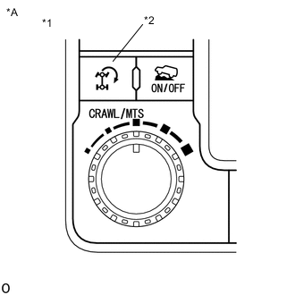
Text in Illustration *A for RHD *1 Integration Control and Panel Assembly *2 Turn Assist Function Switch Push and hold the turn assist function switch (integration control and panel assembly).
-
Check that the turn assist indicator light comes on.
-
Release the turn assist function switch (integration control and panel assembly) to turn the turn assist indicator light off.
-
-
w/o Entry and Start System:
CRAWL ON/OFF Switch / CRAWL Speed Selector Switch (Suspension Control Switch) Check
-
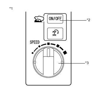
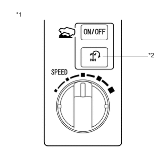
Text in Illustration *1 Suspension Control Switch *2 CRAWL ON/OFF Switch *3 CRAWL Speed Selector Switch Push the CRAWL ON/OFF switch (suspension control switch).
Tech Tips
The CRAWL indicator light illuminates while the CRAWL ON/OFF switch (suspension control switch) is pushed.
-
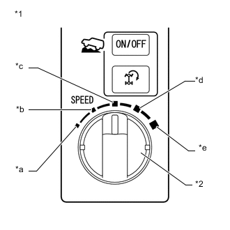
Text in Illustration *1 Suspension Control Switch *2 CRAWL Speed Selector Switch *a Low *b Medium-low *c Medium *d Medium-high *e High Turn the CRAWL speed selector switch (suspension control switch) to low.
-
Turn the CRAWL speed selector switch (suspension control switch) to medium-low.
-
Turn the CRAWL speed selector switch (suspension control switch) to medium.
-
Turn the CRAWL speed selector switch (suspension control switch) to medium-high.
-
Turn the CRAWL speed selector switch (suspension control switch) to high.
-
Turn the CRAWL speed selector switch (suspension control switch) to low.
-
-
w/ Entry and Start System:
CRAWL ON/OFF Switch / CRAWL Speed Selector Switch / Multi-terrain Select Mode Switch (Integration Control and Panel Assembly) Check
-
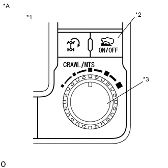
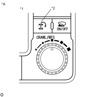
Text in Illustration *A for LHD *1 Integration Control and Panel Assembly *2 CRAWL ON/OFF Switch *3 CRAWL speed selector switch / multi-terrain select mode switch (w/ Multi-terrain Select) 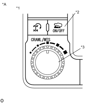
Text in Illustration *A for RHD *1 Integration Control and Panel Assembly *2 CRAWL ON/OFF Switch *3 CRAWL speed selector switch / multi-terrain select mode switch (w/ Multi-terrain Select) Push the CRAWL ON/OFF switch (integration control and panel assembly).
Tech Tips
The CRAWL indicator light illuminates while the CRAWL ON/OFF switch (integration control and panel assembly) is pushed.
-
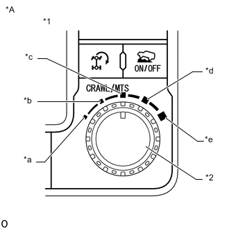
Text in Illustration *A for LHD *1 Integration Control and Panel Assembly *2 CRAWL speed selector switch / multi-terrain select mode switch (w/ Multi-terrain Select) *a Low *b Medium-low *c Medium *d Medium-high *e High 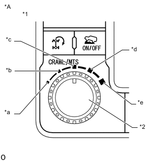
Text in Illustration *A for RHD *1 Integration Control and Panel Assembly *2 CRAWL speed selector switch / multi-terrain select mode switch (w/ Multi-terrain Select) *a Low *b Medium-low *c Medium *d Medium-high *e High Turn the CRAWL speed selector switch / multi-terrain select mode switch (integration control and panel assembly) to low.
-
Turn the CRAWL speed selector switch / multi-terrain select mode switch* (integration control and panel assembly) to medium-low.
-
Turn the CRAWL speed selector switch / multi-terrain select mode switch* (integration control and panel assembly) to medium.
-
Turn the CRAWL speed selector switch / multi-terrain select mode switch* (integration control and panel assembly) to medium-high.
-
Turn the CRAWL speed selector switch / multi-terrain select mode switch* (integration control and panel assembly) to high.
-
Turn the CRAWL speed selector switch / multi-terrain select mode switch* (integration control and panel assembly) to low.
-
*: w/ Multi-terrain Select
-
-
-
w/o Entry and Start System:
VSC OFF Switch Check
-
Press the VSC OFF switch.
-
Check that the VSC OFF indicator light comes on.
-
Press the VSC OFF switch again to turn the VSC OFF indicator light off.
-
-
w/ Entry and Start System:
VSC OFF Switch (Integration control and panel assembly) Check
-
Press the VSC OFF switch (integration control and panel assembly).
-
Check that the VSC OFF indicator light comes on.
-
Press the VSC OFF switch (integration control and panel assembly) again to turn the VSC OFF indicator light off.
-
-
End of Signal Check
-
If the signal check is completed, the ABS warning light and slip indicator light blink (0.125 seconds on and 0.125 seconds off) when the vehicle is stopped and goes off while driving the vehicle.
Note
If the signal check is not completed, the ABS warning light blinks while driving and the ABS does not operate.
-
-
Read test mode (signal check) DTCs.
-
Read the DTC(s) by following the GTS screen.
Note
-
If only DTCs other than test mode signal check DTCs are output, repair the malfunctions and clear the DTCs.
-
If test mode signal check DTCs and other DTCs are output or if only test mode sensor check DTCs are output, repair the malfunctions, clear the DTCs, and perform the test mode inspection again.
Tech Tips
Refer to Signal Check DTCs.
-
-
Turn the ignition switch off and disconnect the GTS.
-
-
-
LIST OF TEST MODE (SIGNAL CHECK) DTC
ABS DTC Code Detection Item Trouble Area C1271 Front Speed Sensor RH Output Voltage Malfunction
-
Front speed sensor RH
-
Sensor installation
-
Speed sensor rotor
C1272 Front Speed Sensor LH Output Voltage Malfunction
-
Front speed sensor LH
-
Sensor installation
-
Speed sensor rotor
C1273 Rear Speed Sensor RH Output Voltage Malfunction
-
Rear speed sensor RH
-
Sensor installation
-
Speed sensor rotor
C1274 Rear Speed Sensor LH Output Voltage Malfunction
-
Rear speed sensor LH
-
Sensor installation
-
Speed sensor rotor
C1275 Abnormal Change in Output Signal of Front Speed Sensor RH
-
Front speed sensor RH
-
Speed sensor rotor
C1276 Abnormal Change in Output Signal of Front Speed Sensor LH
-
Front speed sensor LH
-
Speed sensor rotor
C1277 Abnormal Change in Output Signal of Rear Speed Sensor RH
-
Rear speed sensor RH
-
Speed sensor rotor
C1278 Abnormal Change in Output Signal of Rear Speed Sensor LH
-
Rear speed sensor LH
-
Speed sensor rotor
C1279 G Sensor Output Voltage Malfunction
-
Sensor installation
-
Harness or connector
-
Yaw rate and acceleration sensor (Airbag sensor assembly)
-
CAN communication system
C1281 Master Cylinder Pressure Sensor Output Malfunction Master cylinder solenoid (Master cylinder pressure sensor) C1282 Center Differential Lock Position Switch Malfunction
-
Harness or connector
-
Transfer system
VSC DTC Code Detection Item Trouble Area C1379 Malfunction in CRAWL switch
-
CRAWL ON/OFF switch / CRAWL speed selector switch (Suspension control switch)*1
-
CRAWL ON/OFF switch / CRAWL speed selector switch / multi-terrain select mode switch*3 (Integration control and panel assembly)*2
-
Harness or connector
-
Skid control ECU (Master cylinder solenoid)
-
*1: w/o Entry and Start System
-
*2: w/ Entry and Start System
-
*3: w/ Multi-terrain Select
-