CAN COMMUNICATION SYSTEM(for RHD without Central Gateway ECU) PRECAUTION
-
IGNITION SWITCH EXPRESSION
Tech Tips
The type of ignition switch used on this model differs according to the specifications of the vehicle. The expressions listed in the table below are used in this section.
Expression Ignition Switch (Position) Engine Switch (Condition) Ignition Switch off Off Off (Lock) Ignition Switch ACC ACC On (ACC) Ignition Switch ON ON On (IG) Engine Start START On (Start) -
CAN COMMUNICATION SYSTEM TROUBLESHOOTING
-
Because the order of diagnosis is important to allow correct diagnosis, make sure to begin troubleshooting using How to Proceed with Troubleshooting when CAN communication system related DTCs are output Click here.
-
-
PRECAUTIONS FOR STEERING SYSTEM HANDLING
-
Be careful when replacing parts. Incorrect replacement could affect the performance of the steering system and result in hazardous driving.
-
-
PRECAUTIONS FOR SRS AIRBAG SYSTEM HANDLING
-
This vehicle is equipped with a Supplemental Restraint System (SRS) which includes parts such as airbags for the driver and front passenger. Failure to carry out service operations in the correct sequence could cause unexpected SRS deployment during servicing and may cause a serious accident. Before servicing (including removal or installation of parts, inspection or replacement), be sure to read Precaution for SRS Click here.
-
-
BUS LINE REPAIR
-
After repairing a bus line with solder, wrap the repaired part with electrical tape.
Note
-
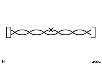
The CANL bus line and CANH bus line must be installed together at all times.
-
When installing, make sure that these lines are twisted, because CAN bus lines are likely to be influenced by electrical noise if the bus lines are not twisted.
-
Leave approximately 80 mm (3.15 in.) loose in the twisted wires around the connector.
-
When repairing the CAN bus lines, do not change the length of the lines. (Make sure that the length of the CANH bus line and CANL bus line are the same.)
-
-
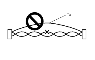
Text in Illustration *a Bypass Wire Do not use bypass wiring between connectors.
Note
-
The ability of the twisted bus lines to resist interference will be lost if bypass wiring is used.
-
Do not use a twisted pair of wires for bypass wiring.
-
-
-
CONNECTOR HANDLING
-
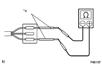
Text in Illustration *a Tester Probe When checking resistance with a tester, insert the tester probes from the backside (harness side) of the connector.
-
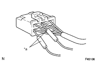
Text in Illustration *a Service Wire Use service wires to check the connector if it is impossible to check continuity from the rear of the connector.
-
-
PRECAUTIONS FOR INSPECTING OR REPLACING CAN JUNCTION CONNECTOR
-
If the CAN junction connector is removed from the vehicle for inspection or replacement, make sure to install the CAN junction connector and all wire harnesses to their original locations with tape and clamps.
-
-
PRECAUTIONS WHEN REPLACING A GATEWAY FUNCTION EQUIPPED ECU (SUB BUS MONITOR ECU OR CENTRAL GATEWAY ECU) WITH A USED ONE FROM ANOTHER VEHICLE
-
When a gateway function equipped ECU (main body ECU (multiplex network body ECU), driving support ECU assembly or central gateway ECU) that was previously installed on another vehicle is used as a replacement part, it is necessary to initialize the connection information stored in the ECU.
Note
If the connection information stored in a gateway function equipped ECU that was previously installed on another vehicle is different from the actual ECUs and sensors connected to the corresponding bus, communication DTCs will be detected.
Tech Tips
When an ECU is replaced with one from a vehicle with the same options and specifications (the same connections to the corresponding bus), initialization of ECU connection information is not necessary.
-
Initialize the connection information of a gateway function equipped ECU (sub bus monitor ECU or central gateway ECU).
-
Connect the GTS to the DLC3.
-
Turn the ignition switch to ON.
-
Turn the GTS on.
-
Enter the following menus: Body Electrical / Main Body / Utility
-
Select Initialization from Utility to initialize the ECU.
-
-
PRECAUTIONS FOR WHEN GATEWAY FUNCTION EQUIPPED ECU (SUB BUS MONITOR ECU OR CENTRAL GATEWAY ECU) DETECTS COMMUNICATION DTCS FOR ECUS NOT CONNECTED TO THE ECU
-
Refer to Precautions when replacing a gateway function equipped ECU (sub bus monitor ECU or central gateway ECU) with a used one from another vehicle and initialize the connection information of the ECU.
-
Clear the DTCs and check that no DTCs are output.
-
-
ACCESSORY PARTS CONNECTED TO OPTION CONNECTOR
-
Some accessory parts connected to the option connector contain equipment connected to CAN communication.
-
Accessory parts only have a function which receives CAN communication signals and do not have a function which sends signals to the CAN bus main line.
-
Even if the GTS is used to perform a bus check, accessory parts are not displayed.
-
Even if the GTS is used to check for DTCs, accessory parts DTCs are not displayed.
-
-