FRONT STABILIZER BAR(w/ KDSS) INSTALLATION

PROCEDURE
-
INSTALL FRONT NO. 1 SUSPENSION CONTROL BLEEDER PLUG
-
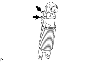
Install the 2 suspension control bleeder plugs to the front stabilizer control cylinder.
- Torque:
- 8.3 N*m { 85 kgf*cm, 73 in.*lbf }
-
-
INSTALL FRONT STABILIZER CONTROL CYLINDER
-
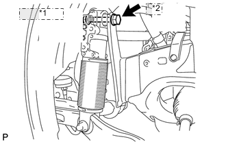
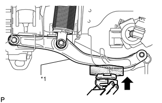
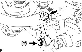
*1 Nut and Washer *2 Bolt Install the front stabilizer control cylinder to the frame with the bolt, washer and nut.
- Torque:
- 275 N*m { 2804 kgf*cm, 203 ft.*lbf }
-
-
CONNECT FRONT NO. 1 STABILIZER CONTROL TUBE ASSEMBLY
-
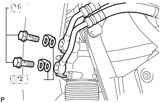
*1 Union Bolt *2 Gasket Install 2 new gaskets and the front stabilizer control cylinder to the front stabilizer control cylinder with the 2 union bolts.
- Torque:
- 69 N*m { 704 kgf*cm, 51 ft.*lbf }
-
-
INSTALL EXHAUST CENTER PIPE ASSEMBLY
-
for 1GR-FE:
Install the center exhaust pipe Click here.
-
for 1UR-FE:
Install the center exhaust pipe Click here.
-
for 3UR-FE:
Install the center exhaust pipe Click here.
-
for 1VD-FTV (w/ DPF):
Install the center exhaust pipe Click here.
-
for 1VD-FTV (w/o DPF):
Install the center exhaust pipe Click here.
-
-
INSTALL TAILPIPE ASSEMBLY
-
for 1GR-FE:
Install the tailpipe Click here.
-
for 1UR-FE:
Install the tailpipe Click here.
-
for 3UR-FE:
Install the tailpipe Click here.
-
for 1VD-FTV (w/ DPF):
Install the tailpipe Click here.
-
for 1VD-FTV (w/o DPF):
Install the tailpipe Click here.
-
-
INSTALL STABILIZER CONTROL TUBE PROTECTOR
-
Install the tube protector with the 2 bolts.
- Torque:
- 15 N*m { 152 kgf*cm, 11 ft.*lbf }
-
-
TEMPORARILY INSTALL FRONT STABILIZER CONTROL ARM ASSEMBLY
-
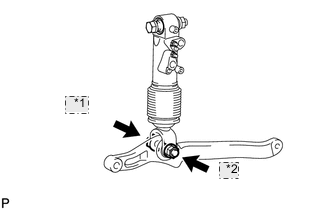
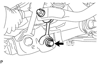
*1 Bolt *2 Nut Temporarily install the stabilizer control arm to the front stabilizer control cylinder with the nut and bolt.
-
-
BLEED AIR FROM SUSPENSION FLUID
-
Bleed the air from the suspension fluid Click here.
-
-
INSTALL FRONT NO. 1 STABILIZER BAR BUSH
-
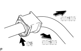
*1 Outer Side *2 Bump *3 Front Side Install the 2 bushes to the outer side of the bush stoppers on the front stabilizer bar as shown in the illustration.
Note
Be sure to install the front No. 1 stabilizer bar bushes so that the bump of each bush faces the inside of the vehicle.
-
-
TEMPORARILY INSTALL FRONT STABILIZER BAR
-
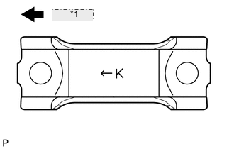
*1 Front Side Set the stabilizer bracket so that the arrow mark is facing the front side of the vehicle.
-
Temporarily install the 2 stabilizer brackets and front stabilizer bar with the 4 bolts.
-

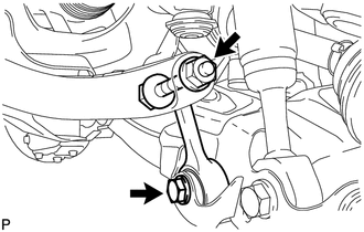
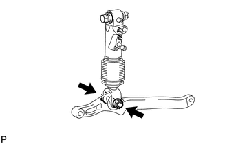
*1 Bolt *2 Nut Temporarily install the front stabilizer bar to the stabilizer control arm with the bolt and nut.
-
-
TEMPORARILY INSTALL FRONT STABILIZER LINK ASSEMBLY RH
-
*1 Nut *2 Bolt Temporarily install the stabilizer link with the bolt.
-
Temporarily install the stabilizer link with the nut.
-
Tighten the nut.
- Torque:
- 128 N*m { 1305 kgf*cm, 94 ft.*lbf }
Tech Tips
If the ball joint turns together with the nut, use a 6 mm hexagon wrench to hold the stud bolt.
-
-
TEMPORARILY INSTALL FRONT STABILIZER LINK ASSEMBLY LH
-
Temporarily install the stabilizer link to the lower arm with the bolt.
-
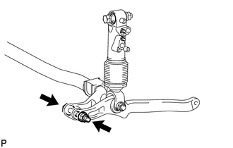
*1 Stabilizer Control Arm Temporarily install the stabilizer link to the stabilizer control arm with the bolt and nut.
Tech Tips
If the front stabilizer control cylinder extends and it is difficult to temporarily install the stabilizer link to the stabilizer control arm, raise the stabilizer control arm with a jack and temporarily install the stabilizer link.
-
-
TIGHTEN FRONT NO. 1 STABILIZER BRACKET LH
-
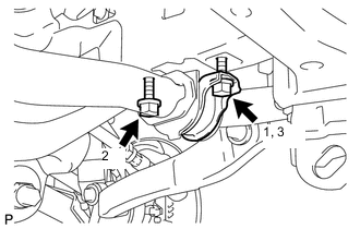
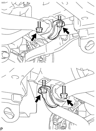
Tighten the 2 bolts of the front stabilizer brackets.
- Torque:
- 87 N*m { 887 kgf*cm, 64 ft.*lbf }
Note
Tighten the bolts in 3 steps, in the order shown in the illustration.
-
-
TIGHTEN FRONT NO. 1 STABILIZER BRACKET RH
-
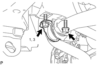
Tighten the 2 bolts of the front stabilizer brackets.
- Torque:
- 87 N*m { 887 kgf*cm, 64 ft.*lbf }
Note
Tighten the bolts in 3 steps, in the order shown in the illustration.
-
-
INSTALL NO. 1 ENGINE UNDER COVER SUB-ASSEMBLY
-
INSTALL FRONT FENDER SPLASH SHIELD SUB-ASSEMBLY LH
-
INSTALL FRONT FENDER SPLASH SHIELD SUB-ASSEMBLY RH
-
STABILIZE SUSPENSION
-
TIGHTEN FRONT STABILIZER LINK ASSEMBLY LH
Note
Perform this procedure with all 4 wheels on the ground.
-
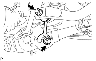
*1 Nut *2 Bolt Tighten the bolt.
- Torque:
- 135 N*m { 1377 kgf*cm, 100 ft.*lbf }
-
Tighten the nut.
- Torque:
- 140 N*m { 1428 kgf*cm, 103 ft.*lbf }
-
-
TIGHTEN FRONT STABILIZER LINK ASSEMBLY RH
-
*1 Bolt Tighten the bolt.
- Torque:
- 135 N*m { 1376 kgf*cm, 100 ft.*lbf }
Note
Perform this procedure with all 4 wheels on the ground.
-
-
TIGHTEN FRONT STABILIZER CONTROL ARM ASSEMBLY
-
Tighten the nut.
- Torque:
- 190 N*m { 1937 kgf*cm, 140 ft.*lbf }
Note
Perform this procedure with all 4 wheels on the ground.
-
-
TIGHTEN FRONT STABILIZER BAR
-
Tighten the nut.
- Torque:
- 230 N*m { 2345 kgf*cm, 170 ft.*lbf }
Note
Perform this procedure with all 4 wheels on the ground.
-
-
INSTALL FRONT FENDER APRON TRIM PACKING D
-
INSTALL FRONT FENDER APRON TRIM PACKING B
-
INSPECT FOR SUSPENSION FLUID LEAK
-
MEASURE VEHICLE HEIGHT
-
CLOSE STABILIZER CONTROL WITH ACCUMULATOR HOUSING SHUTTER VALVE
-
INSTALL STABILIZER CONTROL VALVE PROTECTOR
-
INSPECT FOR EXHAUST GAS LEAK