CAUTION / NOTICE / HINT
-
Use the same procedures for the RH side and LH side.
-
The procedures listed below are for the LH side.
-
A bolt without a torque specification is shown in the standard bolt chart (Click here).
PROCEDURE
-
Click here
TEMPORARILY INSTALL FRONT SHOCK ABSORBER WITH COIL SPRING
-
Temporarily install the upper side of the shock absorber to the chassis frame with the 4 nuts.
-
Temporarily install the lower side of the shock absorber to the lower suspension arm with the bolt and nut.
-
- Click here
CONNECT NO. 2 SUSPENSION CONTROL PRESSURE HOSE (w/ Active Height Control)
-
Apply MP grease to the O-ring and back -up ring of the suspension control pressure hose.
-
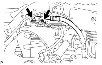
Connect the suspension control pressure hose to the shock absorber with the 2 bolts.
18 N*m 184 kgf*cm 13 ft.*lbf Note:Do not allow any foreign matter such as dirt and dust to enter the suspension control pressure hose from the connecting point.
-
- Click here
BLEED AIR FROM SUSPENSION FLUID (w/ Active Height Control)
- Click here
CHECK FLUID LEVEL IN RESERVOIR (w/ Active Height Control)
- Click here
INSPECT FOR SUSPENSION FLUID LEAK (w/ Active Height Control)
- Click here
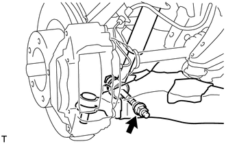
CONNECT STEERING KNUCKLE LH
- Click here
CONNECT SKID CONTROL SENSOR WIRE
- Click here
INSTALL FRONT FENDER APRON TRIM PACKING D (w/ Active Height Control)
-
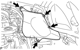
Install the apron trim packing with the 4 clips.
-
- Click here
INSTALL FRONT FENDER APRON TRIM PACKING B (w/ Active Height Control)
-
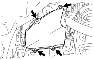
Install the apron trim packing with the 4 clips.
-
- Click here
TEMPORARILY INSTALL FRONT STABILIZER LINK ASSEMBLY RH
-
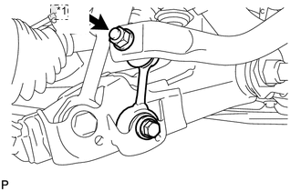
Table 1. *1 Nut Temporarily install the stabilizer link with the bolt.
-
Temporarily install the stabilizer link with the nut.
-
Tighten the nut.
128 N*m 1305 kgf*cm 94 ft.*lbf
-
- Click here
TEMPORARILY INSTALL FRONT STABILIZER LINK ASSEMBLY LH (w/ KDSS)
-
Temporarily install the stabilizer link to the lower arm with the bolt.
-
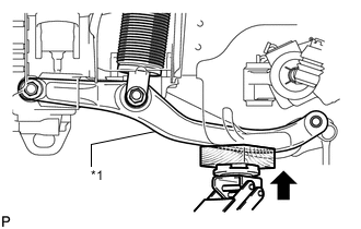
Table 2. *1 Stabilizer Control Arm Temporarily install the stabilizer link to the stabilizer control arm with the bolt and nut.
Tip:If the front stabilizer control cylinder extends and it is difficult to temporarily install the stabilizer link to the stabilizer control arm, raise the stabilizer control arm with a jack and temporarily install the stabilizer link.
-
- Click here
TEMPORARILY INSTALL FRONT STABILIZER LINK ASSEMBLY LH (w/o KDSS)
-
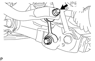
Table 3. *1 Nut Temporarily install the stabilizer link with the nut and bolt.
-
Tighten the nut.
T = 128 N*m{ 1305 kgf*cm }
-
- Click here
TIGHTEN FRONT NO. 1 STABILIZER BRACKET LH
-
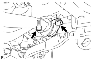
Tighten the 2 bolts of the front stabilizer brackets.
87 N*m 887 kgf*cm 64 ft.*lbf Note:Tighten the bolts in 3 steps, in the order shown in the illustration.
-
- Click here
TIGHTEN FRONT NO. 1 STABILIZER BRACKET RH
-
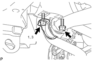
Tighten the 2 bolts of the front stabilizer brackets.
87 N*m 887 kgf*cm 64 ft.*lbf Note:Tighten the bolts in 3 steps, in the order shown in the illustration.
-
- Click here
INSTALL NO. 1 ENGINE UNDER COVER SUB-ASSEMBLY
- Click here
INSTALL FRONT FENDER SPLASH SHIELD SUB-ASSEMBLY LH
- Click here
INSTALL FRONT FENDER SPLASH SHIELD SUB-ASSEMBLY RH
- Click here
STABILIZE SUSPENSION
-
Install the front wheels.
for aluminum wheel 131 N*m 1336 kgf*cm 97 ft.*lbf for steel wheel 209 N*m 2131 kgf*cm 154 ft.*lbf -
Lower the vehicle.
-
Press down on the vehicle several times to stabilize the suspension.
-
-
Click here
TIGHTEN FRONT SHOCK ABSORBER WITH COIL SPRING
-
Tighten the nut.
180 N*m 1835 kgf*cm 133 ft.*lbf Note:Perform this procedure with all 4 wheels on the ground.
-
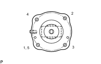
Tighten the 4 upper nuts in diametrically opposite pairs.
45 N*m 459 kgf*cm 33 ft.*lbf -
Check that the first nut that was tightened is at the torque specification.
-
- Click here
TIGHTEN FRONT STABILIZER LINK ASSEMBLY LH (w/ KDSS)
-
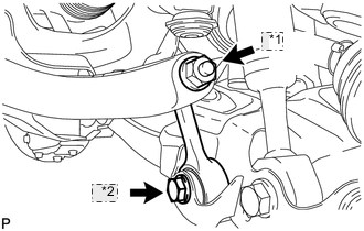
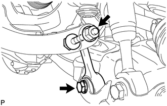
Table 4. *1 Nut *2 Bolt Tighten the bolt.
135 N*m 1377 kgf*cm 100 ft.*lbf -
Tighten the nut.
140 N*m 1428 kgf*cm 103 ft.*lbf Note:Perform this procedure with all 4 wheels on the ground.
-
- Click here
TIGHTEN FRONT STABILIZER LINK ASSEMBLY LH (w/o KDSS)
-
Tighten the bolt.
135 N*m 1377 kgf*cm 100 ft.*lbf Note:Perform this procedure with all 4 wheels on the ground.
-
- Click here
TIGHTEN FRONT STABILIZER LINK ASSEMBLY RH
-
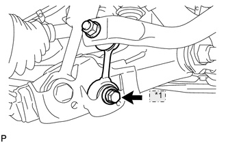
Table 5. *1 Bolt Tighten the bolt.
135 N*m 1377 kgf*cm 100 ft.*lbf Note:Perform this procedure with all 4 wheels on the ground.
-
- Click here
PERFORM VEHICLE HEIGHT OFFSET CALIBRATION (w/ Active Height Control)
-
Perform the vehicle height offset calibration (Click here).
-
- Click here
MEASURE VEHICLE HEIGHT (w/ KDSS)
- Click here
CLOSE STABILIZER CONTROL WITH ACCUMULATOR HOUSING SHUTTER VALVE (w/ KDSS)
- Click here
INSTALL STABILIZER CONTROL VALVE PROTECTOR (w/ KDSS)