STABILIZER CONTROL VALVE(w/ KDSS) INSTALLATION
PROCEDURE
-
INSTALL STABILIZER CONTROL WITH ACCUMULATOR HOUSING ASSEMBLY
-
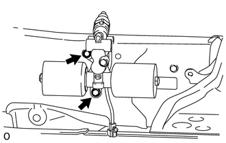
Install the stabilizer control with accumulator housing with the 2 bolts.
- Torque:
- 32 N*m { 326 kgf*cm, 24 ft.*lbf }
-
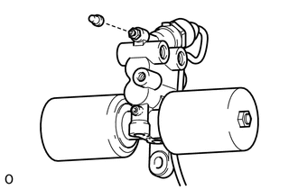
Install the bleeder plug.
- Torque:
- 8.3 N*m { 85 kgf*cm, 73 in.*lbf }
Tech Tips
The bleeder plug cap will be installed after bleeding air.
-
-
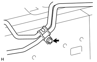
CONNECT REAR NO. 2 STABILIZER CONTROL TUBE ASSEMBLY
-
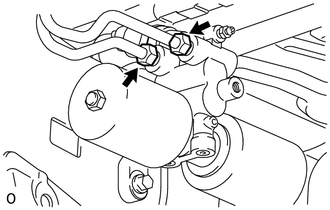
Connect the rear No. 2 stabilizer control tube to the stabilizer control with accumulator housing.
-
-
TEMPORARILY INSTALL REAR NO. 1 STABILIZER CONTROL TUBE ASSEMBLY (for Stabilizer Control Adapter 2 Type)
-
Temporarily install the rear No. 1 stabilizer control tube to the stabilizer control with accumulator housing.
-
Install the bolt to the vehicle.
- Torque:
- 29 N*m { 296 kgf*cm, 21 ft.*lbf }
-
-
TEMPORARILY INSTALL FRONT NO. 2 STABILIZER CONTROL TUBE ASSEMBLY (for Stabilizer Control Adapter 2 Type)
-
Temporarily install the front No. 2 stabilizer control tube to the front No. 1 stabilizer control tube.
-
Install the bolt to the vehicle.
- Torque:
- 29 N*m { 296 kgf*cm, 21 ft.*lbf }
-
-
TEMPORARILY INSTALL FRONT NO. 2 AND REAR NO. 1 STABILIZER CONTROL TUBE ASSEMBLY (for Stabilizer Control Adapter 2 Type)
-
Temporarily install the front No. 2 and rear No. 1 stabilizer control tube to the 2 stabilizer control adapters.
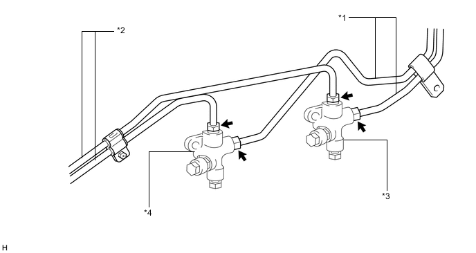
Text in Illustration *1 Rear No. 1 Stabilizer Control Tube *2 Front No. 2 Stabilizer Control Tube *3 Stabilizer Control Adapter for Upper Chamber Side *4 Stabilizer Control Adapter for Lower Chamber Side
-
-
TEMPORARILY INSTALL FRONT NO. 2 STABILIZER CONTROL TUBE ASSEMBLY (for Stabilizer Control Adapter 1 Type)
-
Temporarily install the front No. 2 stabilizer control tube to the front No. 1 stabilizer control tube, stabilizer control adapter for lower chamber side and stabilizer control with accumulator housing assembly.
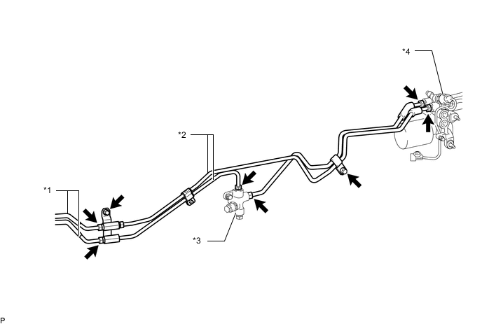
Text in Illustration *1 Front No. 1 Stabilizer Control Tube *2 Front No. 2 Stabilizer Control Tube *3 Stabilizer Control Adapter for Lower Chamber Side *4 Stabilizer Control with Accumulator Housing Assembly -
Install the 2 bolts to the vehicle.
- Torque:
- 29 N*m { 296 kgf*cm, 21 ft.*lbf }
-
-
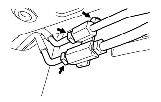
INSTALL STABILIZER CONTROL ADAPTER SUB-ASSEMBLY
-
Install the 2 stabilizer control adapters to the vehicle with the 2 bolts.
- Torque:
- 32 N*m { 326 kgf*cm, 24 ft.*lbf }
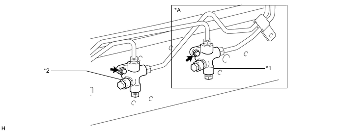
Text in Illustration *A for Stabilizer Control Adapter 2 Type - - *1 Stabilizer Control Adapter for Upper Chamber Side *2 Stabilizer Control Adapter for Lower Chamber Side
-
-
TIGHTEN REAR NO. 1 STABILIZER CONTROL TUBE ASSEMBLY (for Stabilizer Control Adapter 2 Type)
-
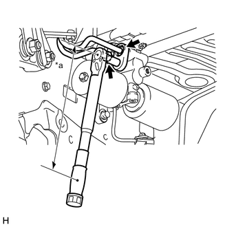
Using a union nut wrench, tighten the rear No. 1 stabilizer control tube.
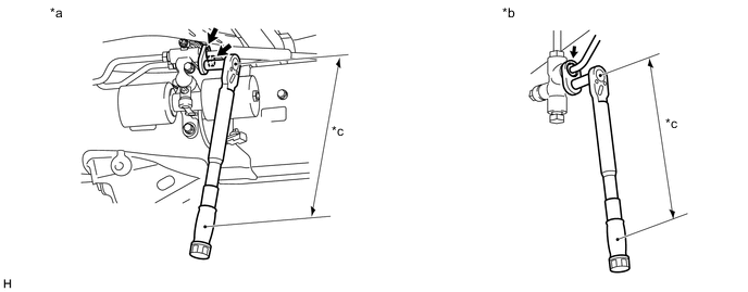
Text in Illustration *a Stabilizer Control with Accumulator Housing Side *b Stabilizer Control Adapter Side *c Torque Wrench Fulcrum Length - - - Torque:
- Specified tightening torque
- 44 N*m { 450 kgf*cm, 33 ft.*lbf }
Tech Tips
-
Calculate the torque wrench reading when changing the fulcrum length of the torque wrench Click here.
-
When using a union nut wrench (fulcrum length of 30 mm (1.181 in.)) + torque wrench (fulcrum length of 255 mm (10.039 in.)): 40 N*m (403 kgf*cm, 29 ft.*lbf)
-
-
TIGHTEN FRONT NO. 2 STABILIZER CONTROL TUBE ASSEMBLY (for Stabilizer Control Adapter 2 Type)
-
Using a union nut wrench, tighten the front No. 2 stabilizer control tube.
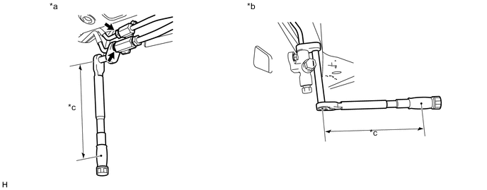
Text in Illustration *a Front No. 1 Stabilizer Control Tube Side *b Stabilizer Control Adapter Side *c Torque Wrench Fulcrum Length - - - Torque:
- Specified tightening torque
- 44 N*m { 450 kgf*cm, 33 ft.*lbf }
Tech Tips
-
Calculate the torque wrench reading when changing the fulcrum length of the torque wrench Click here.
-
When using a union nut wrench (fulcrum length of 30 mm (1.181 in.)) + torque wrench (fulcrum length of 255 mm (10.039 in.)): 40 N*m (403 kgf*cm, 29 ft.*lbf)
-
-
TIGHTEN FRONT NO. 2 STABILIZER CONTROL TUBE ASSEMBLY (for Stabilizer Control Adapter 1 Type)
-
Using a union nut wrench, tighten the front No. 2 stabilizer control tube.
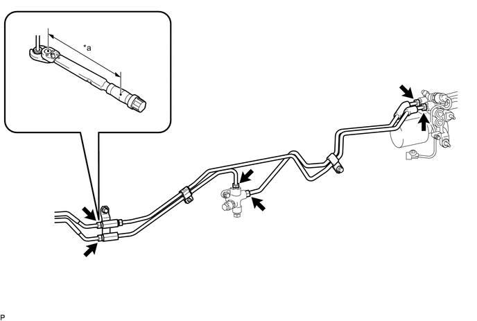
Text in Illustration *a Torque Wrench Fulcrum Length - - - Torque:
- Specified tightening torque
- 44 N*m { 450 kgf*cm, 33 ft.*lbf }
Tech Tips
-
Calculate the torque wrench reading when changing the fulcrum length of the torque wrench Click here.
-
When using a union nut wrench (fulcrum length of 30 mm (1.181 in.)) + torque wrench (fulcrum length of 255 mm (10.039 in.)): 40 N*m (403 kgf*cm, 29 ft.*lbf)
-
-
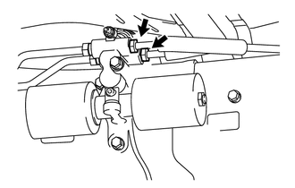
TIGHTEN REAR NO. 2 STABILIZER CONTROL TUBE ASSEMBLY (for Stabilizer Control Adapter 2 Type)
-
Text in Illustration *a Torque Wrench Fulcrum Length Using a union nut wrench, tighten the rear No. 2 stabilizer control tube.
- Torque:
- Specified tightening torque
- 44 N*m { 450 kgf*cm, 33 ft.*lbf }
Tech Tips
-
Calculate the torque wrench reading when changing the fulcrum length of the torque wrench Click here.
-
When using a union nut wrench (fulcrum length of 30 mm (1.181 in.)) + torque wrench (fulcrum length of 255 mm (10.039 in.)): 40 N*m (403 kgf*cm, 29 ft.*lbf)
-
-
INSTALL CENTER EXHAUST PIPE ASSEMBLY
-
for 1GR-FE:
Install the center exhaust pipe Click here.
-
for 1UR-FE:
Install the center exhaust pipe Click here.
-
for 3UR-FE:
Install the center exhaust pipe Click here.
-
for 1VD-FTV:
Install the center exhaust pipe Click here.
-
-
INSTALL TAILPIPE ASSEMBLY
-
for 1GR-FE:
Install the tailpipe Click here.
-
for 1UR-FE:
Install the tailpipe Click here.
-
for 3UR-FE:
Install the tailpipe Click here.
-
for 1VD-FTV:
Install the tailpipe Click here.
-
-
BLEED AIR FROM SUSPENSION FLUID
-
Bleed the air from the suspension fluid Click here.
-
-
INSPECT FOR SUSPENSION FLUID LEAK
-
INSPECT FOR EXHAUST GAS LEAK
-
If gas is leaking, tighten the areas necessary to stop the leak. Replace damaged parts as necessary.
-
-
MEASURE VEHICLE HEIGHT
-
CLOSE STABILIZER CONTROL WITH ACCUMULATOR HOUSING SHUTTER VALVE
Note
-
Perform the inspection on a level surface.
-
Ensure that the wheels are on the ground and facing straight ahead.
-
Perform the inspection with the vehicle load completely on the suspension.
Tech Tips
-
Perform this step with the fuel tank full.
-
If there are any parts installed to the vehicle which place any unbalanced load on the left or right side of the vehicle, remove them.
-
Using a 5 mm socket hexagon wrench or an 8 mm socket wrench, tighten the lower and upper chamber shutter valves of the stabilizer control with accumulator housing.
- Torque:
- 14 N*m { 140 kgf*cm, 10 ft.*lbf }
-
-
INSTALL STABILIZER CONTROL VALVE PROTECTOR
-
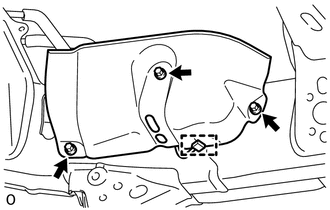
Install the valve protector with the 3 bolts.
- Torque:
- 18 N*m { 184 kgf*cm, 13 ft.*lbf }
-
Attach the clamp, and connect the connector to the valve protector.
-