STABILIZER CONTROL VALVE(w/ KDSS) REMOVAL
PROCEDURE
-
REMOVE STABILIZER CONTROL VALVE PROTECTOR
-
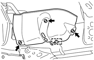
Detach the clamp, and disconnect the connector from the protector.
-
Remove the 3 bolts and protector.
-
-
OPEN STABILIZER CONTROL WITH ACCUMULATOR HOUSING SHUTTER VALVE
-
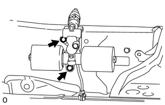
Using a 5 mm socket hexagon wrench or an 8 mm socket wrench, loosen the lower and upper chamber shutter valves of the stabilizer control with accumulator housing 2.0 to 3.5 turns.
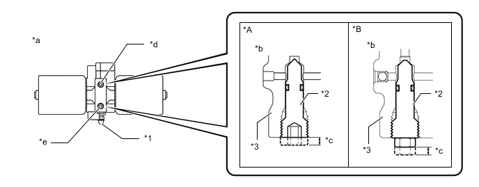
Text in Illustration *A for Type A *B for Type B *1 Bleeder Plug *2 Shutter Valve *3 Block - - *a Bottom view of stabilizer control with accumulator housing *b Side view of stabilizer control with accumulator housing *c 2.0 to 3.5 mm *d Upper Chamber Shutter Valve *e Lower Chamber Shutter Valve - - Note
-
When loosening a shutter valve, make sure that the end protrudes 2 to 3.5 mm (0.0787 to 0.137 in.) from the surface of the block, and do not turn the shutter valve any further.
-
Do not remove the shutter valves.
-
-
-
REMOVE TAILPIPE ASSEMBLY
-
for 1GR-FE:
Remove the tailpipe Click here.
-
for 1UR-FE:
Remove the tailpipe Click here.
-
for 3UR-FE:
Remove the tailpipe Click here.
-
for 1VD-FTV:
Remove the tailpipe Click here.
-
-
REMOVE CENTER EXHAUST PIPE ASSEMBLY
-
for 1GR-FE:
Remove the center exhaust pipe Click here.
-
for 1UR-FE:
Remove the center exhaust pipe Click here.
-
for 3UR-FE:
Remove the center exhaust pipe Click here.
-
for 1VD-FTV:
Remove the center exhaust pipe Click here.
-
-
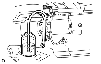
DISCHARGE SUSPENSION FLUID PRESSURE
-
Connect the hose to the bleeder plug for the stabilizer control with accumulator housing and loosen the bleeder plug.
CAUTION:
Be careful as the vehicle height will rapidly decrease when the bleeder plug of the stabilizer control with accumulator housing is loosened.
-
Discharge the suspension fluid from the stabilizer control with accumulator housing.
-
After the fluid pressure has dropped and oil has drained out, tighten the bleeder plug and remove the hose.
- Torque:
- 8.3 N*m { 85 kgf*cm, 73 in.*lbf }
-
-
REMOVE NO. 2 FRONT STABILIZER CONTROL TUBE ASSEMBLY (for Stabilizer Control Adapter 2 Type)
-
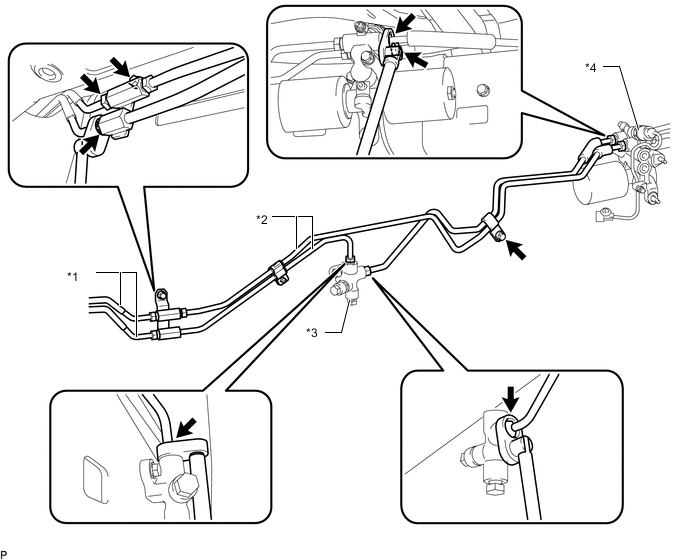
Using a union nut wrench, disconnect the front No. 2 stabilizer control tube from the front No. 1 stabilizer control tube and 2 control adapters.
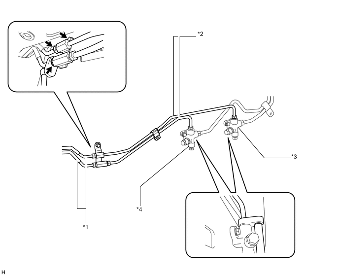
Text in Illustration *1 Front No. 1 Stabilizer Control Tube *2 Front No. 2 Stabilizer Control Tube *3 Stabilizer Control Adapter for Upper Chamber Side *4 Stabilizer Control Adapter for Lower Chamber Side -
Remove the bolt and front No. 2 stabilizer control tube from the vehicle.
-
-
REMOVE FRONT STABILIZER CONTROL TUBE ASSEMBLY NO.2 (for Stabilizer Control Adapter 1 Type)
-
Using a union nut wrench, disconnect the front No. 2 stabilizer control tube from the front No. 1 stabilizer control tube, stabilizer control adapter for lower chamber side and stabilizer control with accumulator housing assembly.
Text in Illustration *1 Front No. 1 Stabilizer Control Tube *2 Front No. 2 Stabilizer Control Tube *3 Stabilizer Control Adapter for Lower Chamber Side *4 Stabilizer Control with Accumulator Housing Assembly -
Remove the bolt and front No. 2 stabilizer control tube from the vehicle.
-
-
REMOVE NO. 1 REAR STABILIZER CONTROL TUBE ASSEMBLY (for Stabilizer Control Adapter 2 Type)
-
Using a union nut wrench, disconnect the rear No. 1 stabilizer control tube from the 2 control adapters and stabilizer control with accumulator housing.
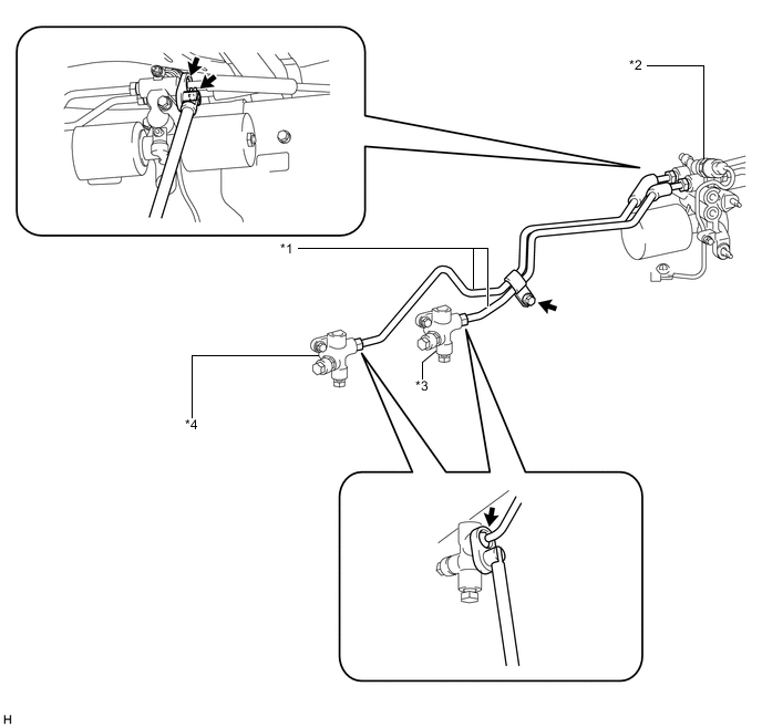
Text in Illustration *1 Rear No. 1 Stabilizer Control Tube *2 Stabilizer Control with Accumulator Housing Assembly *3 Stabilizer Control Adapter for Upper Chamber Side *4 Stabilizer Control Adapter for Lower Chamber Side -
Remove the bolt and rear No. 1 stabilizer control tube from the vehicle.
-
-
DISCONNECT NO. 2 REAR STABILIZER CONTROL TUBE ASSEMBLY
-
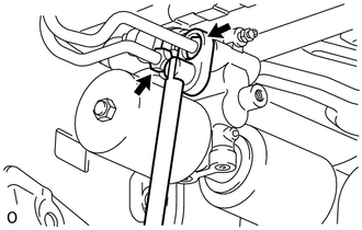
Using a union nut wrench, disconnect the rear No. 2 stabilizer control tube from the stabilizer control with accumulator housing.
-
-
REMOVE STABILIZER CONTROL WITH ACCUMULATOR HOUSING ASSEMBLY
-
Remove the cap and bleeder plug from the accumulator housing.
-
Remove the 2 bolts and stabilizer control with accumulator housing.
-
-
REMOVE STABILIZER CONTROL ADAPTER SUB-ASSEMBLY
-
Remove the 2 bolts and 2 stabilizer control adapters from the vehicle.
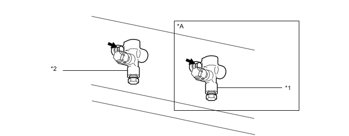
Text in Illustration *A for Stabilizer Control Adapter 2 Type - - *1 Stabilizer Control Adapter for Upper Chamber Side *2 Stabilizer Control Adapter for Lower Chamber Side
-