ACTIVE HEIGHT CONTROL SUSPENSION, Diagnostic DTC:C1719
| DTC Code | DTC Name |
|---|---|
| C1719 | Oil Temperature Sensor Circuit Malfunction |
DESCRIPTION
This circuit is used for sending the data to detect the fluid temperature of the pump. The abnormality of the fluid is judged by the ECU.
| DTC Code | Detection Condition | Trouble Area |
|---|---|---|
| C1719 | When one of the following conditions is met:
|
|
WIRING DIAGRAM
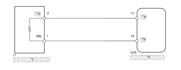
| *a | TOIL |
| *b | STG |
| *c | Fluid Temperature Sensor |
| *d | Suspension Control ECU |
CAUTION / NOTICE / HINT
Note
-
Before performing troubleshooting, inspect the connectors of related circuits.
-
If the suspension control ECU or height control sensor is replaced, the vehicle height offset calibration must be performed Click here.
PROCEDURE
-
READ VALUE USING INTELLIGENT TESTER (OIL TEMPERATURE SENSOR)
-
Connect the intelligent tester to the DLC3.
-
Turn the engine switch on (IG) and the tester on.
-
Select the Data List mode on the intelligent tester.
-
Check the fluid temperature value of the temperature sensor displayed on the intelligent tester.
AHC Tester Display Measurement Item/Range Normal Condition Diagnostic Note Oil Temperature Sensor Fluid temperature sensor reading /
min.: -3276.8°C (-5866.24°F)
max.: 3276.7°C (5930.06°F)
Actual fluid temperature - OK Same as actual fluid temperature
NG 
CHECK HARNESS AND CONNECTOR (TEMPERATURE SENSOR - SUSPENSION CONTROL ECU) Click here
OK 
-
-
RECONFIRM DTC OUTPUT
-
Clear the DTCs Click here.
-
Perform a road test.
-
Check for DTCs.
Result Result Proceed to DTC C1719 is output A DTC C1719 is not output B
A 
REPLACE SUSPENSION CONTROL ECU Click here
B
USE SIMULATION METHOD TO CHECK Click here
-
-
CHECK HARNESS AND CONNECTOR (TEMPERATURE SENSOR - SUSPENSION CONTROL ECU)
Note
When inspecting the wire harness between the suspension control ECU and temperature sensor, it is difficult to determine the malfunctioning area if there is a sensor power supply malfunction. Therefore, disconnect the connectors for the temperature sensor, the acceleration sensors (front RH, front LH) and pressure accumulator sensor on the ECU side.
-
Disconnect the K34 and K35 ECU connectors.
-
Disconnect the i1 sensor connector.
-
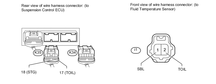
Measure the resistance according to the value(s) in the table below.
Standard Resistance Tester Connection Condition Specified Condition K35-17 (TOIL) - i1-2 (TOIL) Always Below 1 Ω K35-17 (TOIL) - Body ground Always 10 kΩ or higher K35-18 (STG) - i1-1 (SBL) Always Below 1 Ω K35-18 (STG) - Body ground Always 10 kΩ or higher
NG
REPAIR OR REPLACE HARNESS OR CONNECTOR
OK
-
-
INSPECT FLUID TEMPERATURE SENSOR
-
Connect the i2 temperature sensor connector.
-
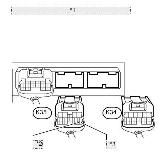
*1 Rear view of wire harness connector: (to Suspension Control ECU) *2 18 (STG) *3 17 (TOIL) Disconnect the K34 and K35 ECU connectors.
-
Measure the resistance according to the value(s) in the table below.
Standard Resistance Tester Connection Condition Specified Condition K35-17 (TOIL) - K35-18 (STG) 20°C (68°F) 2.32 to 2.59 kΩ
OK
REPLACE SUSPENSION CONTROL ECU Click here
NG
REPLACE HEIGHT CONTROL PUMP AND MOTOR Click here
-