ACTIVE HEIGHT CONTROL SUSPENSION, Diagnostic DTC:C1715, C1716, C1717, C1796, C1797, C1798
| DTC Code | DTC Name |
|---|---|
| C1715 | Front Acceleration Sensor RH Malfunction |
| C1716 | Front Acceleration Sensor LH Malfunction |
| C1717 | Rear Acceleration Sensor Malfunction |
| C1796 | Front Acceleration Sensor RH Malfunction (Test Mode DTC) |
| C1797 | Front Acceleration Sensor LH Malfunction (Test Mode DTC) |
| C1798 | Rear Acceleration Sensor Malfunction (Test Mode DTC) |
DESCRIPTION
The acceleration sensor (up and down G sensor) detects the upward and downward acceleration of the vehicle, and outputs it as a voltage to the suspension control ECU. Up and down G sensors are installed in 3 locations: 1) the suspension control ECU, 2) the driver side instrument panel, and 3) the passenger side instrument panel. Each up and down G sensor independently detects the upward and downward acceleration. During a test mode inspection, the suspension control ECU reads the fluctuations in the signal of each sensor. When the sensor cannot detect +/-1.96 m/s2for 1 second or more during test mode, DTCs C1796, C1797 and C1798 are stored.
| DTC Code | Detection Condition | Trouble Area |
|---|---|---|
| C1715 C1796 |
When either of the following conditions is met:
|
|
| C1716 C1797 |
When either of the following conditions is met:
|
|
| C1717 C1798 |
When either of the following conditions is met:
|
Suspension control ECU (Houses rear acceleration sensor) |
WIRING DIAGRAM
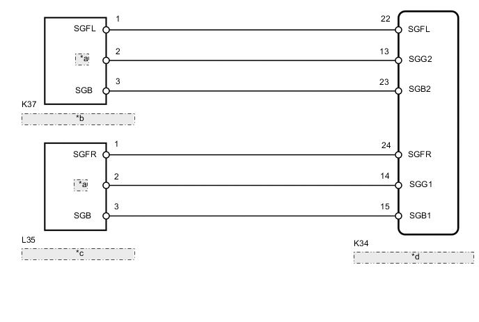
| *a | SGG |
| *b | Front Acceleration Sensor LH |
| *c | Front Acceleration Sensor RH |
| *d | Suspension Control ECU (Houses Rear Acceleration Sensor) |
CAUTION / NOTICE / HINT
Note
-
Before performing troubleshooting, inspect the connectors of related circuits.
-
If the suspension control ECU or height control sensor is replaced, the vehicle height offset calibration must be performed Click here.
-
If DTCs C1717 and C1798 (Rear Acceleration Sensor Malfunction) are stored, replace the suspension control ECU (houses rear acceleration sensor).
PROCEDURE
-
CHECK ACCELERATION SENSOR (DATA LIST)
-
Turn the engine switch off.
-
Connect the intelligent tester to the DLC3.
-
Turn the engine switch on (IG) and the tester on.
-
Enter the following menus: Chassis / AHC / Data List.
-
According to the display on the tester, read the Data List.
AHC Tester Display Measurement Item/Range Normal Condition Diagnostic Note (Up & Down)G Sensor FR G (up and down) front acceleration sensor RH reading/
min.: -1045.29 m/s2
max.: 1045.26 m/s2
0 +/-0.98 m/s2at still condition
Reading changes when vehicle (FR) is bounced (Up & Down)G Sensor FL G (up and down) front acceleration sensor LH reading/
min.: -1045.29 m/s2
max.: 1045.26 m/s2
0 +/-0.98 m/s2at still condition
Reading changes when vehicle (FL) is bounced (Up & Down)G Sensor Rear G (up and down) rear acceleration sensor reading/
min.: -1045.29 m/s2
max.: 1045.26 m/s2
0 +/-0.98 m/s2at still condition
Reading changes when vehicle (rear) is bounced OK Reading changes when vehicle is bounced.
NG 
CHECK HARNESS AND CONNECTOR (ACCELERATION SENSOR - SUSPENSION CONTROL ECU) Click here
OK 
-
-
RECONFIRM DTC OUTPUT
-
Clear the DTCs Click here.
-
Perform a road test.
-
Check for DTCs.
Result Result Proceed to DTC is output A DTC is not output B
B 
USE SIMULATION METHOD TO CHECK Click here
A
-
-
CHECK HARNESS AND CONNECTOR (ACCELERATION SENSOR - SUSPENSION CONTROL ECU)
Note
When inspecting the wire harnesses between the suspension control ECU and acceleration sensors, it is difficult to determine the malfunctioning area if there is a sensor power supply malfunction. Therefore, disconnect the connectors for the acceleration sensors (front RH, front LH), the fluid temperature sensor, and fluid pressure sensor on the ECU side.
-
Check the front acceleration sensor RH side: (C1715)
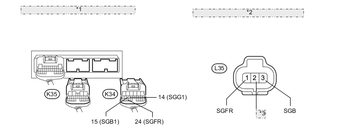
*1 Rear view of wire harness connector: (to Suspension Control ECU) *2 Front view of wire harness connector: (to Front Acceleration Sensor RH) *3 SGG
-
Disconnect the K34 and K35 ECU connectors.
-
Disconnect the L35 sensor connector.
-
Measure the resistance according to the value(s) in the table below.
Standard Resistance Tester Connection Condition Specified Condition L35-1 (SGFR) - K34-24 (SGFR) Always Below 1 Ω L35-2 (SGG) - K34-14 (SGG1) Always Below 1 Ω L35-3 (SGB) - K34-15 (SGB1) Always Below 1 Ω K34-24 (SGFR) - Body ground Always 10 kΩ or higher K34-14 (SGG1) - Body ground Always 10 kΩ or higher K34-15 (SGB1) - Body ground Always 10 kΩ or higher
-
-
Check the front acceleration sensor LH side: (C1716)
-
Disconnect the K34 and K35 ECU connectors.
-
Disconnect the K37 sensor connector.
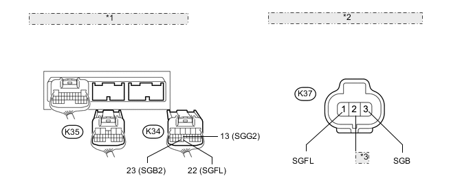
*1 Rear view of wire harness connector: (to Suspension Control ECU) *2 Front view of wire harness connector: (to Front Acceleration Sensor LH) *3 SGG -
Measure the resistance according to the value(s) in the table below.
Standard Resistance Tester Connection Condition Specified Condition K37-1 (SGFL) - K34-22 (SGFL) Always Below 1 Ω K37-2 (SGG) - K34-13 (SGG2) Always Below 1 Ω K37-3 (SGB) - K34-23 (SGB2) Always Below 1 Ω K34-22 (SGFL) - Body ground Always 10 kΩ or higher K34-13 (SGG2) - Body ground Always 10 kΩ or higher K34-23 (SGB2) - Body ground Always 10 kΩ or higher
-
NG
REPAIR OR REPLACE HARNESS OR CONNECTOR
OK
-
-
INSPECT ACCELERATION SENSOR
-
Turn the engine switch off.
-
Remove the front acceleration sensor Click here.
Note
Do not drop the acceleration sensor. If it is dropped, replace it with a new one.
-
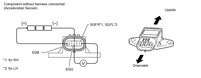
Connect 3 1.5 V dry cell batteries in series.
-
Connect the positive (+) end of the batteries to terminal 3 (SGB) of the acceleration sensor and the negative (-) end of the batteries to terminal 2 (SGG). Then measure the voltage between terminal 1 (SGFR*1, SGFL*2) and terminal 2 (SGG).
Tech Tips
*1: for RH
*2: for LH
Note
Do not apply a voltage of more than 6 V.
Tech Tips
The voltage may differ according to the amount that the sensor is tilted.
Standard Voltage for RH Tester Connection Condition Specified Condition 1 (SGFR) - 2 (SGG) Sensor stationary Approx. 2.0 to 2.5 V Sensor is tilted Change between approx. 0.9 to 2.3 V for LH Tester Connection Condition Specified Condition 1 (SGFL) - 2 (SGG) Sensor stationary Approx. 2.0 to 2.5 V Sensor is tilted Change between approx. 0.9 to 2.3 V
OK
REPLACE SUSPENSION CONTROL ECU Click here
NG
REPLACE ACCELERATION SENSOR Click here
-