REAR DIFFERENTIAL CARRIER ASSEMBLY(w/ Differential Lock) REASSEMBLY

PROCEDURE
-
INSPECT DIFFERENTIAL SIDE GEAR BACKLASH
-
Install the 2 thrust washers to the 2 side gears.
-
Install the 4 thrust washers to the 4 pinion gears.
-
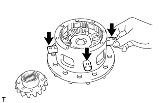
Install the 2 side gears into the differential case.
-
Install the holder into the differential case.
-
Install the 4 pinion gears.
-
Align the holes of the differential case and pinion shaft, and install the 3 pinion shafts.
-
Align the matchmarks and install the differential cover to the differential case.
-
Temporarily install the 5 bolts and 3 pinion shaft pins.
-
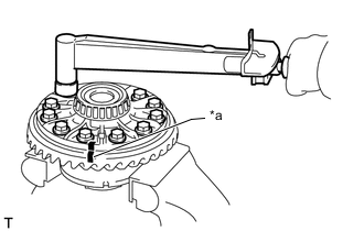
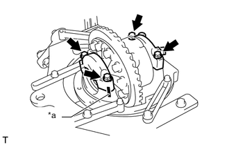
Using a T10 "TORX" socket, tighten the 5 bolts and 3 pinion shaft pins.
- Torque:
- 58 N*m { 590 kgf*cm, 43 ft.*lbf }
-
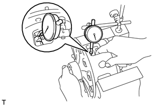
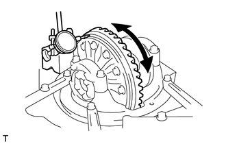
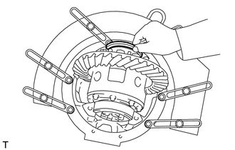
Using a dial indicator, while holding the side gear, measure the backlash.
Standard backlash 0.02 to 0.15 mm (0.000788 to 0.00590 in.) If the backlash is not within the specification, replace the side gear thrust washers with washers of a different thickness.
Tech Tips
-
Make sure the washers on both sides are the same size.
-
Measure at all 4 pinion gear locations.
-
Apply hypoid gear oil to each sliding surface and rotating part.
Standard Washer Thickness Part No. Specified Condition Part No. Specified Condition 41361-60680 1.53 to 1.57 mm (0.0603 to 0.0618 in.) 41361-60740 1.83 to 1.87 mm (0.0721 to 0.0736 in.) 41361-60690 1.58 to 1.62 mm (0.0622 to 0.0637 in.) 41361-60750 1.88 to 1.92 mm (0.0741 to 0.0755 in.) 41361-60700 1.63 to 1.67 mm (0.0642 to 0.0657 in.) 41361-60760 1.93 to 1.97 mm (0.0760 to 0.0775 in.) 41361-60710 1.68 to 1.72 mm (0.0662 to 0.0677 in.) 41361-60770 1.98 to 2.02 mm (0.0780 to 0.0795 in.) 41361-60720 1.73 to 1.77 mm (0.0682 to 0.0696 in.) 41361-60780 2.03 to 2.07 mm (0.0800 to 0.0814 in.) 41361-60730 1.78 to 1.82 mm (0.0701 to 0.0716 in.) 41361-60790 2.08 to 2.12 mm (0.0819 to 0.0834 in.) -
-
After measuring the backlash, remove the 5 set bolts and 3 pinion shaft pins.
-
-
ASSEMBLE DIFFERENTIAL CASE
-
Clean the threads of the bolts, pinion shaft pins, case and cover with non-residue solvent.
-
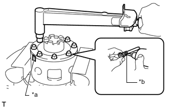
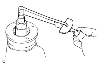
Text in Illustration *a Matchmark *b Adhesive Coat the threads of the bolts and pinion shafts with adhesive.
Adhesive Toyota Genuine Adhesive 1324, Three Bond 1324 or equivalent -
Align the matchmarks of the case and cover.
-
Using a T10 "TORX" socket, install the 5 bolts and 3 pinion shaft pins.
- Torque:
- 58 N*m { 590 kgf*cm, 43 ft.*lbf }
-
-
INSTALL REAR DIFFERENTIAL CASE BEARING
-
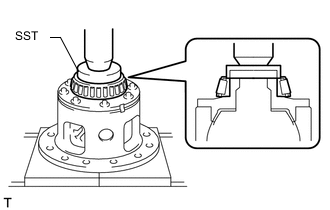
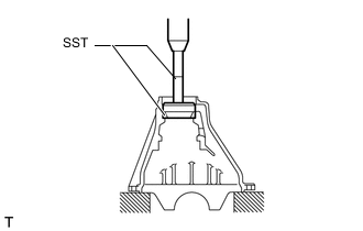
Differential Cover Side:
Using SST and a press, press the side bearing onto the differential cover.
- SST
- 09550-60010
-
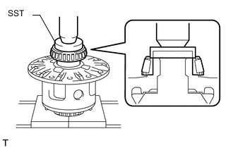
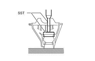
Ring Gear Side:
Using SST and a press, press the side bearing onto the differential case.
- SST
- 09550-60010
-
-
INSTALL DIFFERENTIAL RING GEAR
-
Clean the threads of the bolts and differential case with non-residue solvent.
-
Clean the contact surface of the differential case and ring gear.
-
Heat the ring gear to about 100°C (212°F) in boiling water.
-
Carefully take the ring gear out of the boiling water.
-
After the moisture on the ring gear has completely evaporated, quickly align the matchmarks on the ring gear and differential case and set the ring gear onto the differential case. Then temporarily install the 12 bolts so that the bolt holes in the ring gear and differential case are aligned.
-
Text in Illustration *a Matchmark After the ring gear cools down sufficiently, remove the 12 bolts. Then apply thread lock adhesive to the 12 bolts and install them.
Thread lock Toyota Genuine Adhesive 1360K, Three Bond 1360K or equivalent - Torque:
- 137 N*m { 1397 kgf*cm, 101 ft.*lbf }
-
-
INSPECT RUNOUT OF DIFFERENTIAL RING GEAR
-
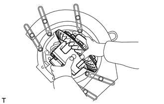
Place the bearing outer races on their respective bearings.
Tech Tips
Do not interchange the left and right outer races.
-
Install the assembled plate washers to the side bearing.
-
Install the differential case to the differential carrier.
Tech Tips
If it is difficult to install the differential case to the carrier, replace the plate washer with a thinner one.
However, select a plate washer that allows no clearance between it and the carrier.
-
Align the matchmarks on the bearing caps and differential carrier.
-
Install and uniformly tighten the 4 bolts a little at a time.
-
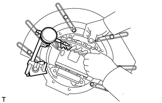
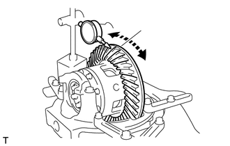
Using a dial indicator, check the ring gear runout.
Maximum runout 0.05 mm (0.00197 in.) If the runout is more than the maximum, replace the ring gear.
-
Remove the differential case.
-
-
INSTALL REAR DRIVE PINION FRONT TAPERED ROLLER BEARING
-
Using SST and a press, press in the front bearing outer race.
- SST
- 09950-60020 ( 09951-00710 )
- 09950-70010 ( 09951-07150 )
-
-
INSTALL REAR DRIVE PINION REAR TAPERED ROLLER BEARING
-
Using SST and a press, press in the rear bearing outer race.
- SST
- 09950-60020 ( 09951-00890 )
- 09950-70010 ( 09951-07150 )
-
-
INSTALL REAR DRIVE PINION REAR TAPERED ROLLER BEARING
-
Install the washer to the drive pinion.
Tech Tips
After installing the washer, check the tooth contact pattern. If necessary, replace the washer with one of a different thickness.
-
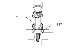
Text in Illustration *1 Plate Washer Using SST and a press, press the rear bearing into the drive pinion.
- SST
- 09506-35010
-
-
INSPECT DRIVE PINION PRELOAD
-
Install the drive pinion and front bearing.
Tech Tips
Assemble the spacer and oil seal after adjusting the gear contact pattern.
-
Install the oil slinger.
-

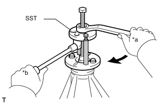
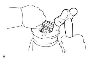
Text in Illustration *a Turn *b Hold Using SST, install the companion flange.
- SST
- 09950-30012 ( 09951-03010, 09953-03010, 09954-03010, 09955-03030, 09956-03040 )
-
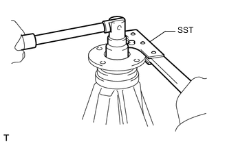
Using SST to hold the companion flange in place, then slowly tighten the nut within the drive pinion preload adjustment range so that it reaches the specified drive pinion preload (at Starting).
- SST
- 09330-00021 ( 09330-00030 )
Limit Torque Value 441 N*m (4497 kgf*cm, 325 ft.*lbf) or less Note
-
Coat the nut and threads of the drive pinion with gear oil.
-
As there is no spacer, tighten the nut a little at a time, being careful not to overtighten it.
-
Using a torque wrench, measure the preload.
Standard Preload (at Starting) Bearing Specified Condition New 0.73 to 1.38 N*m (8 to 14 kgf*cm, 7 to 12 in.*lbf) Reused 0.54 to 1.06 N*m (6 to 10 kgf*cm, 5 to 9 in.*lbf) Note
Measure the total preload after turning the bearing clockwise and counterclockwise several times to make the bearing smooth.
-
-
INSTALL REAR DIFFERENTIAL CASE SUB-ASSEMBLY
-
Place the bearing outer races on their respective bearings.
Tech Tips
Do not interchange the left and right outer races.
-
Install the assembled plate washer to the side bearing.
-
Install the differential case to the carrier.
-
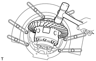
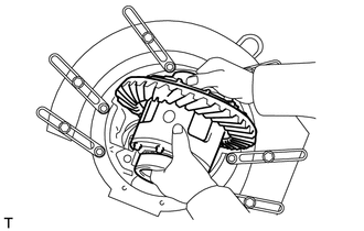
Using a plastic-faced hammer, tap on the ring gear to make sure the differential case is aligned with the carrier, and fit the bearings and plate washers into the carrier.
Tech Tips
If it is difficult to install the differential case to the carrier, replace the plate washer with a thinner one.
However, select a plate washer that allows no clearance between it and the carrier.
-
-
INSPECT DIFFERENTIAL RING GEAR BACKLASH
-
Using a dial indicator, measure the backlash while holding the side bearing of the ring gear side.
Standard backlash 0.10 to 0.20 mm (0.00394 to 0.00787 in.) -
Select a case cover side plate washer using the backlash as a reference.
Standard Side Plate Washer Thickness Part No. Mark No. Specified Condition Part No. Mark No. Specified Condition 90201-79001 01 2.66 to 2.68 mm (0.1048 to 0.1055 in.) 90201-79013 13 3.02 to 3.04 mm (0.1189 to 0.1196 in.) 90201-79002 02 2.69 to 2.71 mm (0.1059 to 0.1066 in.) 90201-79014 14 3.05 to 3.07 mm (0.1201 to 0.1208 in.) 90201-79003 03 2.72 to 2.74 mm (0.1071 to 0.1078 in.) 90201-79015 15 3.08 to 3.10 mm (0.1213 to 0.1220 in.) 90201-79004 04 2.75 to 2.77 mm (0.1083 to 0.1090 in.) 90201-79016 16 3.11 to 3.13 mm (0.1225 to 0.1232 in.) 90201-79005 05 2.78 to 2.80 mm (0.1095 to 0.1102 in.) 90201-79017 17 3.14 to 3.16 mm (0.1237 to 0.1244 in.) 90201-79006 06 2.81 to 2.83 mm (0.1107 to 0.1114 in.) 90201-79018 18 3.17 to 3.19 mm (0.1248 to 0.1255 in.) 90201-79007 07 2.84 to 2.86 mm (0.1119 to 0.1125 in.) 90201-79019 19 3.20 to 3.22 mm (0.1260 to 0.1267 in.) 90201-79008 08 2.87 to 2.89 mm (0.1130 to 0.1137 in.) 90201-79020 20 3.23 to 3.25 mm (0.1272 to 0.1279 in.) 90201-79009 09 2.90 to 2.92 mm (0.1142 to 0.1149 in.) 90201-79021 21 3.26 to 3.28 mm (0.1284 to 0.1291 in.) 90201-79010 10 2.93 to 2.95 mm (0.1154 to 0.1161 in.) 90201-79022 22 3.29 to 3.31 mm (0.1296 to 0.1303 in.) 90201-79011 11 2.96 to 2.98 mm (0.1166 to 0.1173 in.) 90201-79023 23 3.32 to 3.34 mm (0.1307 to 0.1314 in.) 90201-79012 12 2.99 to 3.01 mm (0.1178 to 0.1185 in.) - - - -
Select a ring gear teeth side plate washer so that there is no clearance between the outer race and case.
-
Remove the 2 plate washers and differential carrier.
-
Install the selected plate washer into the lower part of the carrier.
-
Place the selected plate washer onto the differential case together with the outer races, and install the differential case with the outer races to the carrier.
-
Using a plastic-faced hammer, tap on the ring gear to make sure the differential case is aligned with the carrier, and fit the bearings and plate washers into the carrier.
-
Using a dial indicator, measure the ring gear backlash.
Standard backlash 0.10 to 0.20 mm (0.00394 to 0.00787 in.) If the backlash is not within the specification, adjust it by either increasing or decreasing the thickness of washers on both sides by an equal amount.
Tech Tips
There should be no clearance between the plate washers and case.
-
Ensure that there is ring gear backlash.
-
-
ADJUST SIDE BEARING PRELOAD
-
Remove the ring gear side plate washer.
-
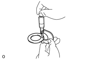
Using a micrometer, measure the thickness.
-
Using the backlash as a reference, select a washer that is 0.06 to 0.09 mm (0.00237 to 0.00354 in.) thicker than the removed washer.
Tech Tips
Select a washer which can be pressed in 2/3 of the full amount with your finger.
-
Install the selected plate washer.
-
Using SST and plastic-faced hammer, tap the plate washer so that it fits to the bearing.
- SST
- 09504-22012
-
Text in Illustration *a Matchmark Align the matchmarks on the caps and carrier.
-
Install the 4 bearing cap bolts to the specified torque.
- Torque:
- 113 N*m { 1152 kgf*cm, 83 ft.*lbf }
-
Using a dial indicator, adjust the ring gear backlash until it is within the specification.
Standard backlash 0.10 to 0.20 mm (0.00394 to 0.00787 in.)
-
-
INSPECT TOTAL PRELOAD
-
Using a torque wrench, measure the preload with the teeth of the drive pinion and ring gear in contact.
Standard Total Preload (at starting) Bearing Specified Condition New 1.02 to 1.87 N*m (11 to 19 kgf*cm, 10 to 16 in.*lbf) Reused 0.83 to 1.55 N*m (9 to 15 kgf*cm, 8 to 13 in.*lbf)
-
-
INSPECT TOOTH CONTACT BETWEEN RING GEAR AND DRIVE PINION
-
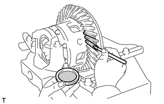
Coat 3 or 4 teeth at 3 different positions on the ring gear with Prussian blue.
-
Turn the companion flange in both directions to inspect the ring gear for proper tooth contact.
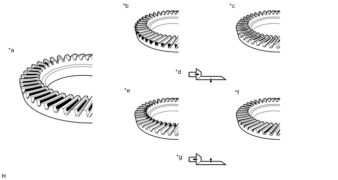
Text in Illustration *a Proper Contact *b Heel Contact *c Face Contact *d Select an adjusting washer that will shift the drive pinion closer to the ring gear (*b, *c) *e Toe Contact *f Flank Contact *g Select an adjusting washer that will shift the drive pinion away from the ring gear (*e, *f) - - If the teeth are not contacting properly, use the following table to select a proper washer for correction.
Standard Washer Thickness Part No. Specified Condition Part No. Specified Condition 90564-40004 1.04 to 1.06 mm (0.0410 to 0.0417 in.) 90564-40016 1.315 to 1.335 mm (0.0518 to 0.0525 in.) 90564-40006 1.065 to 1.085 mm (0.0420 to 0.0427 in.) 90564-40017 1.34 to 1.36 mm (0.0528 to 0.0535 in.) 90564-40007 1.09 to 1.11 mm (0.0430 to 0.0437 in.) 90564-40018 1.365 to 1.385 mm (0.0538 to 0.0545 in.) 90564-40008 1.115 to 1.135 mm (0.0439 to 0.0446 in.) 90564-40019 1.39 to 1.41 mm (0.0548 to 0.0555 in.) 90564-40009 1.14 to 1.16 mm (0.0449 to 0.0456 in.) 90564-40020 1.415 to 1.435 mm (0.0557 to 0.0564 in.) 90564-40010 1.165 to 1.185 mm (0.0459 to 0.0466 in.) 90564-40021 1.44 to 1.46 mm (0.0567 to 0.0574 in.) 90564-40011 1.19 to 1.21 mm (0.0469 to 0.0476 in.) 90564-40022 1.465 to 1.485 mm (0.0577 to 0.0584 in.) 90564-40012 1.215 to 1.235 mm (0.04789 to 0.0486 in.) 90564-40023 1.49 to 1.51 mm (0.0587 to 0.0594 in.) 90564-40013 1.24 to 1.26 mm (0.0489 to 0.0496 in.) 90564-40024 1.515 to 1.535 mm (0.0597 to 0.0604 in.) 90564-40014 1.265 to 1.285 mm (0.0498 to 0.0505 in.) 90564-40025 1.54 to 1.56 mm (0.0607 to 0.0614 in.) 90564-40015 1.29 to 1.31 mm (0.0508 to 0.0515 in.) - -
-
-
REMOVE DRIVE PINION COMPANION FLANGE REAR NUT
-
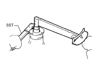
Using SST to hold the flange, remove the nut.
- SST
- 09330-00021 ( 09330-00030 )
-
-
REMOVE REAR DRIVE PINION REAR COMPANION FLANGE SUB-ASSEMBLY
-
REMOVE REAR DIFFERENTIAL DRIVE PINION OIL SLINGER
-
REMOVE REAR DRIVE PINION FRONT TAPERED ROLLER BEARING
-
INSTALL REAR DIFFERENTIAL DRIVE PINION BEARING SPACER
-
Install a new spacer to the drive pinion.
-
-
INSTALL REAR DRIVE PINION FRONT TAPERED ROLLER BEARING
-
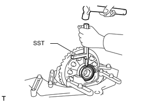
Using SST and a hammer, tap in the bearing (outer race).
- SST
- 09316-60011 ( 09316-00011, 09316-00021 )
-
Install the bearing (inner race).
-
-
INSTALL REAR DIFFERENTIAL DRIVE PINION OIL SLINGER
-
INSTALL REAR DIFFERENTIAL CARRIER OIL SEAL
-
INSTALL REAR DRIVE PINION REAR COMPANION FLANGE SUB-ASSEMBLY
-
Text in Illustration *a Turn *b Hold Using SST, install the companion flange.
- SST
- 09950-30012 ( 09951-03010, 09953-03010, 09954-03010, 09955-03030, 09956-03040 )
-
Coat the threads of a new nut with hypoid gear oil.
-
Using SST to hold the companion flange in place, then slowly tighten the nut within the drive pinion preload adjustment range so that it reaches the specified drive pinion preload (at Starting).
- SST
- 09330-00021 ( 09330-00030 )
Limit Torque Value 441 N*m (4497 kgf*cm, 325 ft.*lbf) or less -
Using a torque wrench, measure the preload.
Standard Preload (at Starting) Bearing Specified Condition New 1.08 to 1.73 N*m (12 to 17 kgf*cm, 10 to 15 in.*lbf) Reused 0.89 to 1.41 N*m (10 to 14 kgf*cm, 8 to 12 in.*lbf)
-
-
INSPECT TOTAL PRELOAD
-
Using a torque wrench, measure the preload with the teeth of the drive pinion and ring gear in contact.
Standard Preload (at Starting) Bearing Specified Condition New 1.37 to 2.22 N*m (14 to 22 kgf*cm, 13 to 19 in.*lbf) Reused 1.18 to 1.90 N*m (13 to 19 kgf*cm, 11 to 16 in.*lbf)
-
-
INSPECT DIFFERENTIAL RING GEAR BACKLASH
-
Using a dial indicator, measure the ring gear backlash.
Standard backlash 0.10 to 0.20 mm (0.00394 to 0.00787 in.) Tech Tips
Measure at 3 or more positions around the circumference of the ring gear.
If the backlash is not as specified, adjust the side bearing preload or repair as necessary.
-
-
INSPECT RUNOUT OF REAR DRIVE PINION REAR COMPANION FLANGE SUB-ASSEMBLY
-
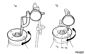
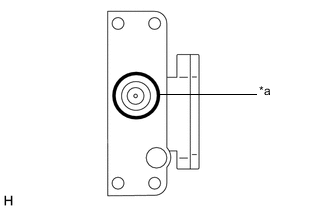
Text in Illustration *a Vertical Runout *b Lateral Runout *c 35 mm (1.38 in.) Using a dial indicator, measure the runout of the companion flange vertically and laterally.
Maximum Runout Runout Specified Condition Vertical runout 0.10 mm (0.00394 in.) Lateral runout 0.10 mm (0.00394 in.) If the runout is more than the maximum, replace the companion flange.
-
-
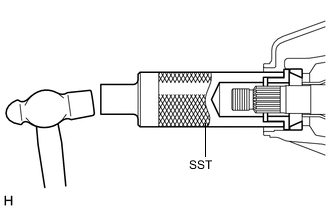
STAKE DRIVE PINION COMPANION FLANGE REAR NUT
-
Using a chisel and hammer, stake the nut.
-
-
INSTALL DIFFERENTIAL LOCK SHIFT ACTUATOR
-
Remove any old FIPG material.
-
Clean the contact surfaces of any residual FIPG material using non-residue solvent.
-
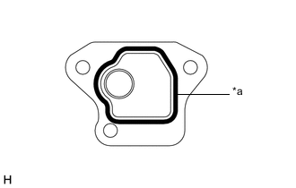
Text in Illustration *a Seal Packing Width: 1 to 2 mm (0.0394 to 0.0315 in.) Apply seal packing to the actuator.
Seal packing Toyota Genuine Seal Packing 1281, Three Bond 1281 or equivalent Tech Tips
Install the actuator within 10 minutes after applying seal packing.
-
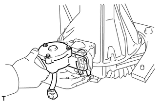
Install the shift fork and actuator to the differential and align the shift fork hole with the shift lock.
-
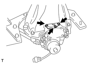
Clean the threads of the set bolt and fork shaft with non-residue solvent.
-
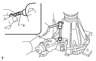
Text in Illustration *a Adhesive Coat the threads of the set bolt with adhesive.
Adhesive Toyota Genuine Adhesive 1324, Three Bond 1324 or equivalent -
Install the shift fork shaft set bolt.
- Torque:
- 20 N*m { 200 kgf*cm, 14 ft.*lbf }
-
Engage the sleeve with the dog clutch of the differential case.
-
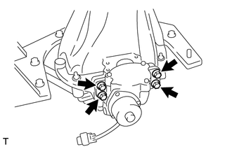
Install the 4 bolts.
- Torque:
- 24 N*m { 245 kgf*cm, 18 ft.*lbf }
-
-
INSTALL REAR DIFFERENTIAL LOCK COVER
-
Remove any old FIPG material.
-
Clean the contact surfaces of any residual FIPG material using non-residue solvent.
-
Text in Illustration *a Seal Packing Width: 1 to 2 mm (0.0394 to 0.0787 in.) Apply seal packing to the cover
Seal packing Toyota Genuine Seal Packing 1281, Three Bond 1281 or equivalent Tech Tips
Install the cover within 10 minutes after applying seal packing.
-
Install the cover with the 3 bolts.
- Torque:
- 18 N*m { 184 kgf*cm, 13 ft.*lbf }
-
-
INSTALL NO. 1 TRANSFER INDICATOR SWITCH